PROTECTION PRODUCTS
1
www.semtech.com
PROTECTION PRODUCTS
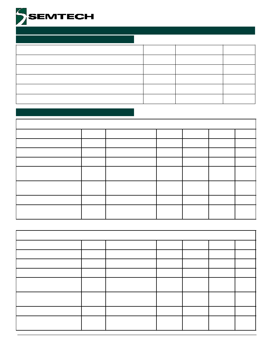
SL05 THRU SL24
Low Capacitance TVS Diode
For High Speed Data Interfaces
Description
Features
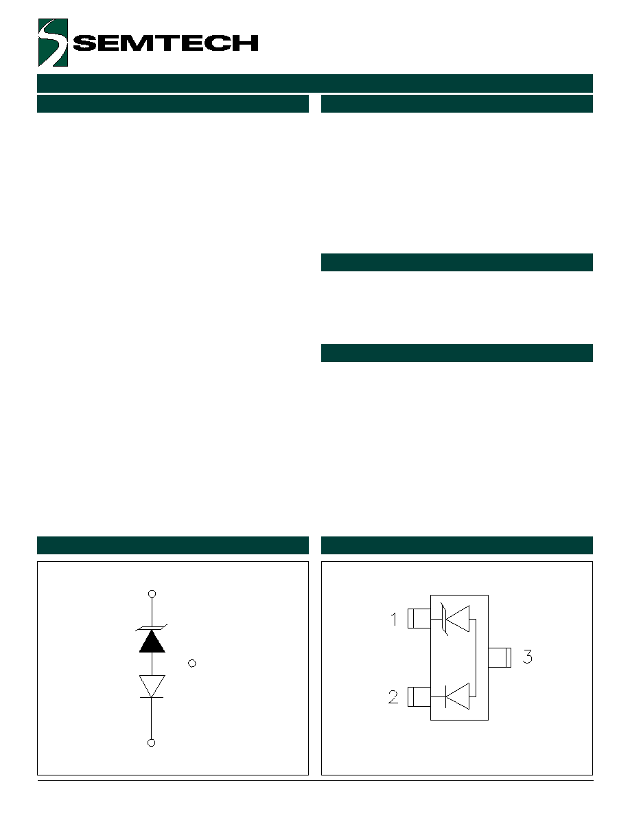
Circuit Diagram
Schematic & PIN Configuration
Revision 9/2000
The SL series of TVS arrays are designed to protect
sensitive electronics from damage or latch-up due to
ESD, lightning, and other voltage-induced transient
events. They are available with operating voltages of
5V, 12V, 15V and 24V.
TVS diodes are solid-state devices designed specifically
for transient suppression. They offer desirable charac-
teristics for board level protection including fast re-
sponse time, low operating and clamping voltage and
no device degradation. The SL series devices feature
a low capacitance, fast switching compensation diode
in series with a standard TVS diode. This effectively
reduces the overall capacitance of the device to less
than 5pF making it an integrated, low capacitance
solution for use on high-speed interfaces.
The SL series devices may be used to meet the immu-
nity requirements of IEC 61000-4-2, level 4.
Applications
Mechanical Characteristics
u
High-Speed data lines
u
Cellular handsets & accessories
u
Universal Serial Bus (USB) port protection
u
Portable instrumentation
u
LAN/WAN equipment
u
Peripherals
u
Transient protection for high-speed data lines to
IEC 61000-4-2 (ESD) 15kV (air), 8kV (contact)
IEC 61000-4-4 (EFT) 40A (5/50ns)
IEC 61000-4-5 (Lightning) 12A (8/20�s)
u
Small package for use in portable electronics
u
Two devices will protect one line
u
Low capacitance for high-speed data lines
u
Working voltages: 5V, 12V, 15V and 24V
u
Solid-state silicon avalanche technology
u
JEDEC SOT23 package
u
Molding compound flammability rating: UL 94V-0
u
Marking : Marking Code
u
Packaging : Tape and Reel per EIA 481
SOT23 Top View
1
2
3
(N.C.)
5
� 2000 Semtech Corp.
www.semtech.com
PROTECTION PRODUCTS
PROTECTION PRODUCTS
SL05 THRU SL24
SL Connection Options
Device Connection for Protection of One High-Speed
Data Line
The SL series devices are designed to protect high-
speed data lines. The SLxx utilizes a low capacitance
compensation diode in series with, but in opposite
polarity to a TVS diode in each line to achieve an
effective capacitance of less than 5pF per device.
During a transient event, the internal rectifier must be
forward biased (TVS is reversed biased). Therefore,
each device will only suppress transient events in one
polarity. To achieve protection in both positive and
negative polarity, a second device is connected in anti-
parallel to the first. On unidirectional lines, a fast
switching steering diode may be used as an alternative
to using two SL devices.
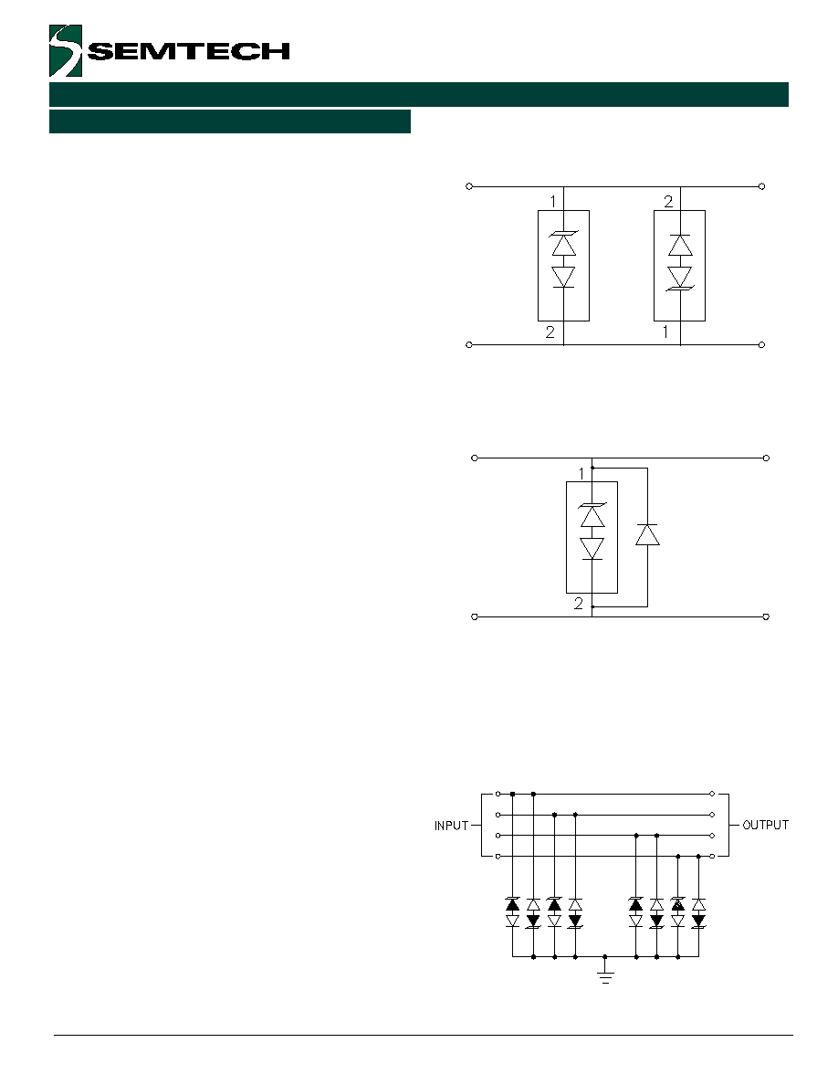
The options for connecting the devices are as follows:
l
Low capacitance protection of one high-speed
line: Protection of one unidirectional or bidirec-
tional high-speed line is achieved by connecting two
devices in anti-parallel. Pin 1 of the first device is
connected to the line and pin 2 is connected to
ground (or to a second line for differential protec-
tion). Pin 2 of the second device is connected to
line 1 and pin 1 is connected to ground (or line 2)
as shown. Pin 3 is not connected. During positive
duration transients, the first device will conduct
from pin 1 to 2. The steering diode conducts in the
forward direction while the TVS will avalanche and
conduct in the reverse direction. During negative
transients, the second device will conduct in the
same manner. For optimum protection, the ground
connections should be made directly to the ground
plane for best results. The path length is kept as
short as possible to reduce the effects of parasitic
inductance in the board traces. The path length
between the TVS and the protected line should
also be minimized.
l
Connection Option for Unidirectional Lines Only:
An optional method for protecting unidirectional
(normal signal polarities above ground) lines is to
add a fast switching steering diode in parallel to the
SL TVS. Input/outputs are connected to pin 1 of
the SL device and the cathode of the rectifier. The
anode of the diode and pin 2 of the SL TVS are
connected to ground.
Two Devices : Bidirectional or
Unidirectional Line
One Devices with Steering Diode :
Unidirectional Line Only
I/O Line Protection
Applications Information