PROTECTION PRODUCTS
1
www.semtech.com
PROTECTION PRODUCTS
STF203-15 THRU STF203-33
USB Upstream Port Filterand TVS
For EMI Filtering and ESD Protection
Description
Features
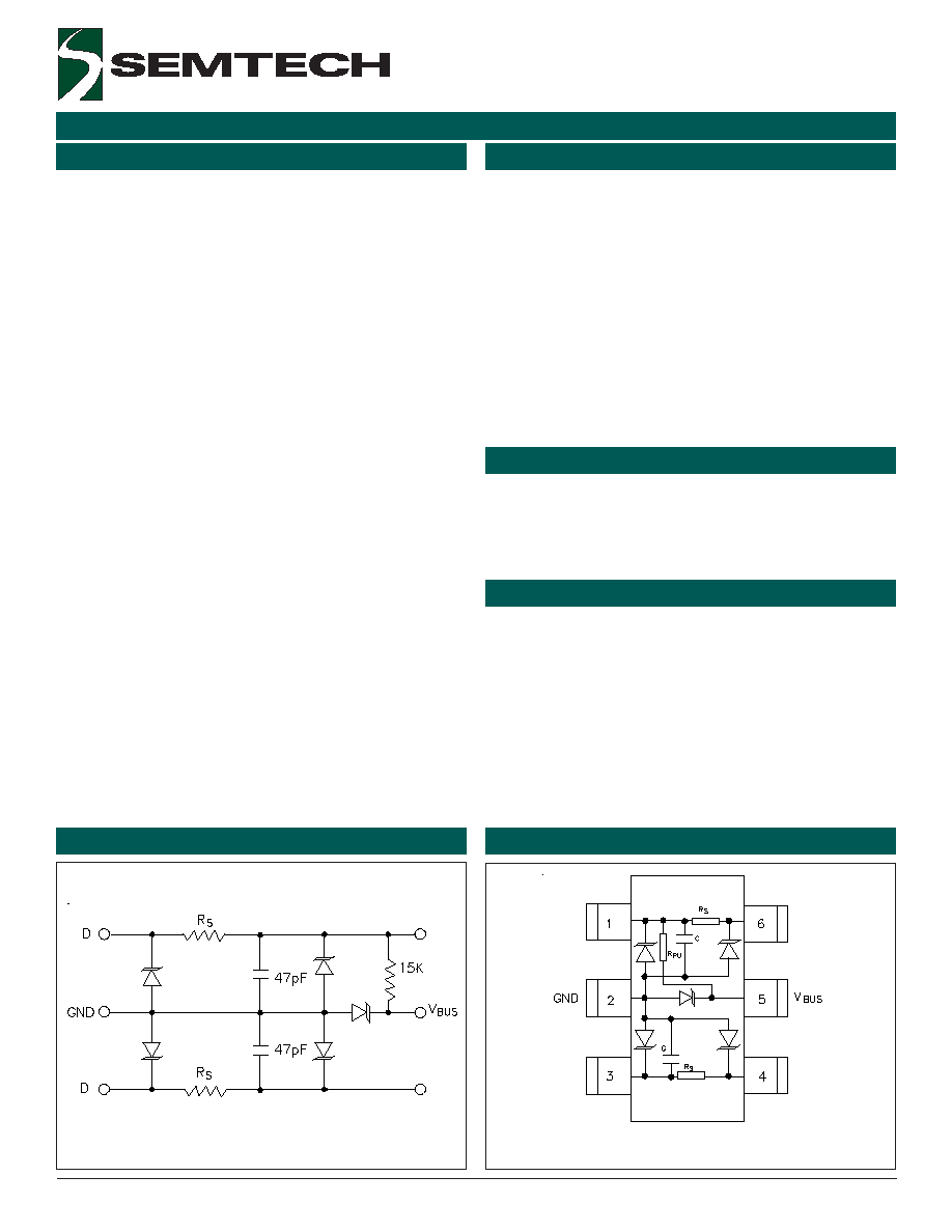
Schematic and PIN Configuration
Revision 05/06/03
The STF203 is a combination EMI filter and line
termination device with integrated TVS diodes for use
on upstream USB ports. It is constructed using a
proprietary technology that allows passive components
and TVS diodes to be integrated in the same package.
Each device will provide termination, filtering, and ESD
protection for one upstream USB port. The STF203 is
an easily implemented solution for meeting the
requirements of revision 1.1 of the Universal Serial Bus
specification.
Line termination is achieved with series resistors on
both the D+ and D- USB lines. The value of series
resistance added to the output impedance of the USB
driver must be as close to possible to the 45
characteristic impedance of the cable (90
balanced)
to minimize transmission line reflections. They are
available with resistor values of 15
(STF203-15),
22
(STF203-22), and 33
(STF203-33). The 1.5k
pull-up resistor is required by the USB specification to
identify the equipment as either a full-speed
(connected to D+ line) or low-speed (connected to D-
line) device. The 47pF capacitors are required to
bypass high frequency energy to ground and to control
the edge rate of the USB signals. The TVS diodes
provide ESD protection of both (D+ and D-) data lines
and the voltage bus (V
BUS
). The TVS diodes on the
input/output pins provide suppression of ESD voltages
in excess of �15kV (air discharge) and �8kV (contact
discharge) per IEC 61000-4-2, level 4. The TVS diode
on the V
BUS
pin will suppress ESD discharges in excess
of 25kV per IEC 61000-4-2.
Applications
Mechanical Characteristics
USB Ports
Cellular Handsets
PDA
Pagers
Digital Cameras
PC Peripherals
MP3 Players
Bidirectional EMI/RFI filtering and line termination
with integrated ESD protection
ESD protection for USB power (V
BUS
) and data lines
(D+ and D-) to
IEC 61000-4-2 (ESD) �15kV (air), �8kV (contact)
IEC 61000-4-4 (EFT) 40A (5/50ns)
Filtering and termination for one USB port
Series resistors: 15
,
22
,
and 33
Low TVS operating voltage (5.25V)
Low leakage current
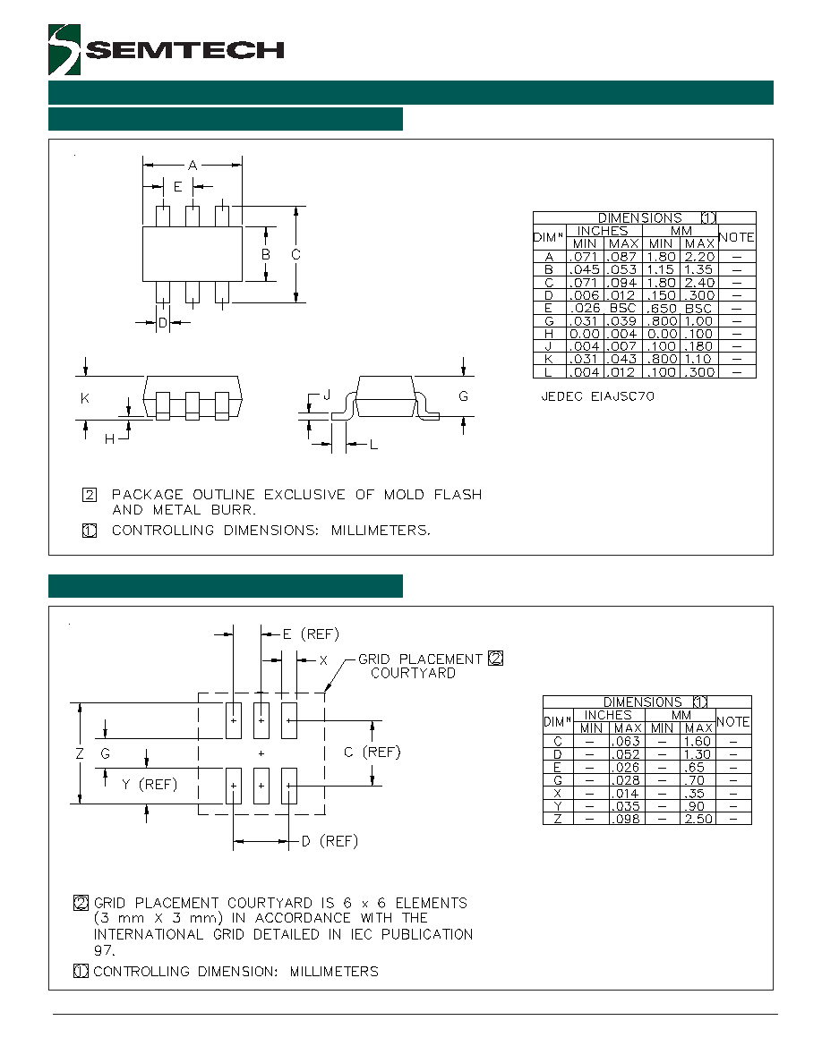
Small SC70-6L package
Solid-state technology
EIAJ SC70-6L package
Molding compound flammability rating: UL 94V-0
Marking : Marking Code
Packaging : Tape and Reel per EIA 481
SC70-6L (Top View)
Circuit Diagram
.
1
5
3
6
2
4
D In/Out
D In/Out
D In/Out
D In/Out
4
2003 Semtech Corp.
www.semtech.com
PROTECTION PRODUCTS
STF203-15 THRU STF203-33
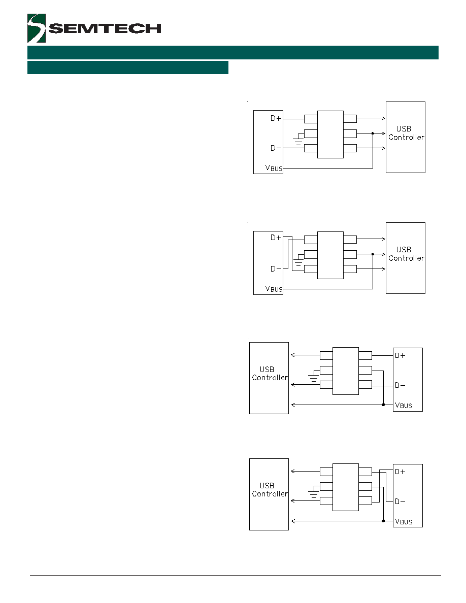
Device Connection
The STF203 is designed to provide termination, EMI
filtering and ESD protection for one USB port. The
device is connected as follows:
1 .
1 .
1 .
1 .
1 . Full-Speed Devices: For full-speed devices the
pull-up resistor is connected to the D+ line. Route
the D+ line from the connector to pin 1 of the
STF203. Pin 6 is connected to the D+ line of the
IC. Route the D- line from the connector to pin 3.
Pin 4 is connected to the D- line of the IC. Pin 5 is
connected to the voltage supply line (V
BUS
). Pin 2 is
connected to ground. Note that the input and
output connections may be reversed if necessary
(See Figure 3).
2 .
2 .
2 .
2 .
2 . Low-Speed Devices::::: For low speed devices the
pull-up resistor is connected to the D- line. Route
the D- line from the connector to pin 1 of the
STF203. Pin 6 is connected to the D- line of the IC.
Route the D+ line from the connector to pin 3. Pin
4 is connected to the D+ line of the IC. Pin 5 is
connected to the voltage supply line (V
BUS
). Pin 2 is
connected to ground. Note that the input and
output connections may be reversed if necessary
(See Figure 4).
USB Port Design Considerations
The Universal Serial Bus (USB) specification requires
termination and filtering components for proper opera-
tion. In addition, an open USB socket is vulnerable to
hazardous ESD discharges in excess of 15kV. These
discharges can occur on the data lines or the voltage
bus. The STF203 is an easily implemented solution
that is designed to meet the termination and EMI filter
requirements of the USB specification revision 1.1. It
also provides ESD protection to IEC 61000-4-2,
level 4.
USB line termination is achieved with series resistors
on both the D+ and D- lines. These resistors preserve
signal integrity by matching the cable impedance to
that of the differential driver. A 1.5k
pull-up resistor
is used to identify an upstream port on either the D+
(full speed devices) or the D- (low speed devices) data
line. Capacitors are used for EMI suppression. TVS
diodes provide ESD protection of both (D+ and D-)
data lines and the voltage bus (V
BUS
). The STF203
integrates all of these components in a small SC-70
package. This integrated solution simplifies design and
requires minimal board space.
Figure 1 - Preferred Connection Diagram
(Full Speed Devices)
Applications Information
Figure 2 - Preferred Connection Diagram
(Low Speed Devices)
1
2
3
4
5
6
STF203
From Connector
1
2
3
4
5
6
STF203
From Connector
Figure 4 - Alternate Connection Diagram
(Low Speed Devices)
Figure 3 - Alternate Connection Diagram
(Full Speed Devices)
1
2
3
4
5
6
STF203
From Connector
1
2
3
4
5
6
STF203
From Connector