 | –≠–ª–µ–∫—Ç—Ä–æ–Ω–Ω—ã–π –∫–æ–º–ø–æ–Ω–µ–Ω—Ç: GP1A05 | –°–∫–∞—á–∞—Ç—å:  PDF PDF  ZIP ZIP |

GP1A05/GP1A22LC/
GP1A23LC/GP1A25LC
OPIC Photointerrupter with
Connector
s
Features
s
Applications
s
Outline Dimensions
1. Uses 3-pin connector terminal
2. High sensing accuracy ( Slit width : 0.5mm )
3. Wide gap between light emitter and detec-
* " OPIC " ( Optical IC ) is a trademark of SHARP
and signal-processing circuit integrated onto a single chip.
tor ( 5mm )
3
3.5
(
9.2
)
g
15.0
34.0
Depth2.0
3.0
7.5
10.5
C0.5
5.0
3.5
GP1A05
2.0
5.0
g
11.0
2
7.0
1
3.5
1
g
1
2
3
3 2 1
g
(2.5)
(2.5)
1
2
3
(5.9)
( 9.9
)
(10.4)
(2.5)
(2.5)
*
( )
:
Reference dimensions
g
JAPAN AMP made
Recommended connectors
on the inserted side
Dimensions(d) Tolerance
d
<
4.0
±
0.2
4.0
<=
d
<
16.0
±
0.3
16
<=
d
±
0.5
2 GND
EI 3-pin connector 171825-3
2 GND
(2.5)
(2.5)
g
2 protrusion of connector
from holder
:
MAX.1.0
g
1 JAPAN SOLDERLESS
TERMINAL MSG. CO.,
LTD. made connector
B3P-SHF-1AA
Recommended connectors
on the inserted side
Terminal
:
SHF-001T-0.8SS
Housing
:
H3P-SHF-AA
2 GND
(2.5)
(2.5)
g
JAPAN SOLDERLESS
TERMINAL MSG. CO.,
LTD. made connector
Recommended connectors
on the inserted side
Housing
:
Terminal
:
(SHF-001T-0.8SS ) etc.
2 GND
g
MOLEX JAPAN CO.,
LTD. made connector
5267-03A
Recommended connectors
on the inserted side
Housing
:
5264-03
Terminal
:
5263PBT
BS3P-SHF-1AA
Corporation. An OPIC consists of a light-detecting element
Slit width 0.5
gg Recommended connectors on the inserted side are show on the following 3rd page.
data books, etc. Contact SHARP in order to obtain the latest version of the device specification sheets before using any SHARP's device.
"
"
In the absence of confirmation by device specification sheets, SHARP takes no responsibility for any defects that occur in equipment using any of SHARP's devices, shown in catalogs,
(Unit : mm )
GP1A05/GP1A22LC/GP1A23LC/GP1A25LC
* Unspecified tolerances shall be as follows
;
* ( )
:
Reference dimensions
* ( )
:
Reference dimensions
* ( )
:
Reference dimensions
1. Copiers, Printers
2. Facsimiles
172053-3 etc.
gg
1 V
CC
3 V
O
12.0
±
0.1
11.0
±
0.1
5.5
±
1.0
4.2
±
0.2
3.0
±
0.1
4.0
+
0
-
0.1
1 V
CC
3 V
O
11.0
±
0.3
1.0
MAX
g
2
5.5
±
1.0
etc.
gg
11.0
±
0.3
1 V
CC
3 V
O
GP1A25LC (Same as GP1A05 except connector )
GP1A23LC (Same as GP1A05 except connector )
(H3P-SHF-AA ) etc
gg
1 V
CC
3 V
O
5.5
±
1.0
11.0
±
0.3
GP1A22LC (Same as GP1A05 except connector )
GP1A05/GP1A22LC/GP1A23LC/GP1A25LC
s
Electro-optical Characteristics
( Unless otherwise specified, Vcc = 5V, Ta = 25∞C)
Parameter
Symbol
V
CC
I
CCL
V
OL
I
CCH
V
OH
f
MIN.
TYP.
MAX.
Unit
4.5
-
5.5
V
-
-
30
mA
-
-
0.35
V
-
-
30
mA
V
CC
x 0.9
-
-
V
-
-
Hz
Conditions
Light beam uninterrupted
Light beam uninterrupted,I
OL
= 16mA
Light beam interrupted
Light beam interrupted,R
L
= 47k
Operating supply voltage
Low level supply current
Low level output voltage
High level supply current
High level output voltage
s
Absoulte Maximum Ratlngs
(Ta = 25∞C )
*2 Collector current of output transistor
*3 The connector should be plugged in/out at normal temperature.
*4 No DC output is allowed.
*4
R
L
= 47k
*5
Response frequency
*5 Response frequency is measured with the disk shown below being rotated. ( Unit : mm )
*1 Collector-emitter voltage of output transistor
Disk
2.0
0.5
0.5
Parameter
Symbol
Rating
Unit
Supply
voltage
GP1A05
V
CC
- 0.5 to + 10
V
- 0.5 to + 8
GP1A22LC / GP1A23LC / GP1A25LC
*1
Output voltage
V
O
- 0.5 to + 28
V
*2
Low level output current
I
OL
50
mA
*3
Operating temperature
T
opr
- 20 to + 75
∞C
tempera-
ture
*3
Storage
GP1A05 / GP1A22LC / GP1A23LC
T
stg
- 40 to + 85
∞C
- 30 to + 85
GP1A25LC
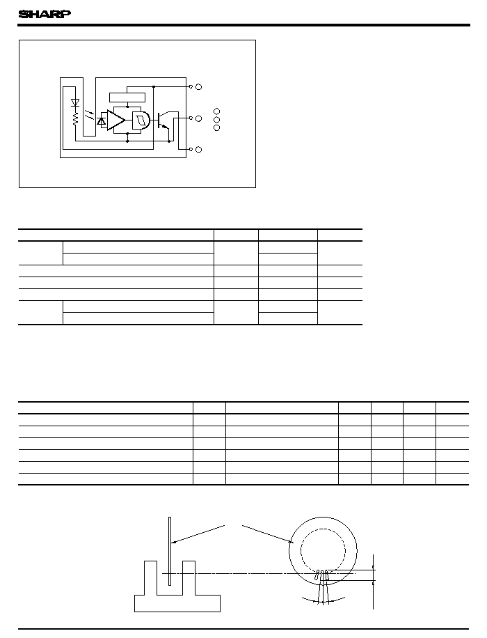
Voltage regulator
3
2
Amp.
1
2 GND
Internal connection diagram ( Common to 4 models )
3 000
1 V
CC
3 V
O

0
25
50
75
100
- 20
60
50
40
30
20
10
0
Ambient temperature Ta ( ∞C)
20
10
0
5.5
5.0
4.5
30
1
10
100
0.6
0.5
0.1
0
0.2
0.3
0.4
0
Shield distance d ( mm )
Ambient temperature Ta ( ∞C)
2
5
20
50
1.0
0.5
0.2
0.1
0.01
0.02
0.05
100
75
50
25
0
-
25
Detecting position d = 3.5 ± 0.3mm
1
2
3
4
5
6
7
Output High
Output Low
Shield
d
h
Shield
Output Low
Output High
7
6
5
4
3
2
1
Shield distance h ( mm )
0
16mA
5mA
+ 25∞C
+ 75∞C
Fig. 2 Low Level Output Voltage vs.
Low Level Output Current
Fig. 1 Low Level Output Current vs.
Ambient Temperature
V
CC
= 5V
Ta = 25∞C
Fig. 3 Low Level Output Voltage vs.
Ambient Temperature
Low levle output voltage V
OL
(
V
)
Supply voltage V
CC
( V)
Supply current I
CC
(
mA
)
I
CCL
I
CCH
Fig. 6 Detecting Position Characteristics (2)
V
CC
= 5V
V
CC
= 5V
Ta = 25∞C
R
L
= 47k
(
GP1A22LC / GP1A23LC / GP1A25LC
: d = 3.5 ± 0.5mm )
V
CC
= 5V
Ta = 25∞C
R
L
= 47k
GP1A05/GP1A22LC/GP1A23LC/GP1A25LC
Fig. 4 Supply Current vs. supply Voltage
Fig. 5 Detecting Position Characteristics (1)
Low level output current I
OL
(
mA
)
Low levle output voltage V
OL
(
V
)
Low level output current I
OL
( mA )
I
OL
= 30mA
T
a
=- 20∞C,+ 25∞C,+ 75∞C
T
a
=- 20∞C
Detecting position h= 3.0
+ 2.0
-
1.5mm

GP1A05/GP1A22LC/GP1A23LC/GP1A25LC
s
Precautions for Use
s
Recommended Connectors on the Inserted Side
<<
GP1A05
>>
q
JAPAN AMP made El series connectors
Housing color
Black
Blue
Green
Red
Housing Model No. 172142-3 2-172142-3 4-172142-3 6-172142-3 8-172142-3
Special
terminal
Model. No.
(Material
:
Copper
phosphide )
AWG
size
Product shape
Model No.
AWG
26 to 22
Bulk
170369-1
Chain
170354-1
AWG
30 to 26
Bulk
170370-1
Chain
170355-1
(standard type )
q
JAPAN AMP made El series connectors
(low profile type )
q
JAPAN AMP made El series connectors
(amp mass termination )
Housing color
Black
Blue
Green
Red
Housing Model No.
2-171822-3 4-171822-3 6-171822-3 8-171822-3
Special
terminal
Model. No.
AWG
size
Product
shape
Material
Model No.
AWG
26 to 20
Bulk
Brass
170204-1
Copper
phosphide
170204-2
Chain
Brass
170262-1
Copper
phosphide
170262-2
AWG
30 to 26
Bulk
Brass
170205-1
Copper
phosphide
170205-2
Chain
Brass
170263-1
Copper
phosphide
170263-2
Housing-terminal
united type
connector
AWG28
(Green)
AWG26
( Natural
color )
AWG24
( Black)
AWG22
(Red)
172054-3 172053-3 172052-3 172051-3
* Terminal Material
:
Copper phosphide
<<
GP1A22LC/ GP1A23LC
>>
een V
CC
and GND
near the device in order to stabilize power supply line.
However, do not perform the above cleaning using a soft cloth with cleaning solvent in the
marking portion.
In this case, use only the following type of cleaning solvent used for wiping off:
Ethyl alcohol, Methyl alcohol, Isopropyl alcohol,
When the cleaning solvents except for specified materials are used, please consult us.
Housing Model No.
H3P-SHF-AA
S3P-SHF-1
Special
terminal
Model. No.
AWG
size
Material
Model No.
AWG
size
Material
Model No.
AWG
26 to 22
Brass
SHF-001T-0.8SS
AWG
27 to 22
Brass
SHF-001T-0.8P
Copper
phosphide
SHF-001T-0.8BS
Copper
phosphide
-
AWG
30 to 26
Brass
SHF-002T-0.8SS
AWG
30 to 28
Brass
SHF-002T-0.8P
Copper
phosphide
SHF-001T-0.8BS
Copper
phosphide
-
171822-3
Natural
color
Natural
color
case; therefore, dip cleaning or ultrasonic cleaning is prohibited.
q
JAPAN SOLDERLESS TERMINAL MSG. CO., LTD. made ( Natural color ∑ bulk )
( 1) It is recommended that a by-pass capacitor of more than 0.01
µ
F be added betw
( 2) In this product, the PWB is fixed with a rear cover, and cleaning solvent may remain inside the
( 3) Remove dust or stains, using an air blower or a soft cloth moistened in cleaning solvent.
( 4) As for other general cautions, refer to the chapter " Precautions for Use .
"
Recommended connectors on the inserted side for GP1A05, GP1A22LC, and GP1A23LC are shown below.