 | –≠–ª–µ–∫—Ç—Ä–æ–Ω–Ω—ã–π –∫–æ–º–ø–æ–Ω–µ–Ω—Ç: GP1U777R | –°–∫–∞—á–∞—Ç—å:  PDF PDF  ZIP ZIP |
GP1U77R Sreies
s
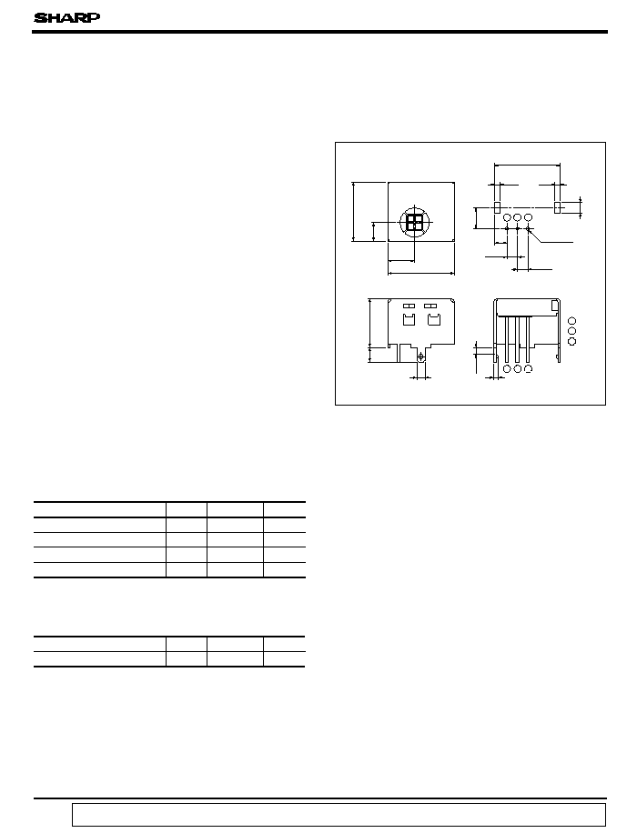
Outline Dimensions
(Unit : mm )
s
Features
s
Applications
s
Absolute Maximum Ratings
(Ta = 25∞C )
s
Recommended Operating Conditions
*1 No dew formation
*2 For 5 seconds
Parameter
Symbol
Rating
Unit
Operating supply voltage
V
CC
0 to 6.3
V
*1
Operating temperature
T
opr
- 10 to + 70
∞C
Storage temperature
T
stg
- 20 to + 70
∞C
*2
Soldering temperature
T
sol
260
∞C
1. Less sensitive to fluorescent lamp driven
by inverter
2. Improved anti-electromagnetic noise char-
acteristic by mesh type light detecting
window.
1. TVs
2. VCRs
16
1.3
1.3
3
2.54
2.54
5.1
3.6
1.6
2
1
Recommended drilling as viewed
from the soldering face.
2.5
1
2
3
3 GND
1
2
3
1 Vcc
2 Vout
12MAX
4. Built-in voltage regulator circuit
g
1
g
1 Detector center
g
1
data books, etc. Contact SHARP in order to obtain the latest version of the device specification sheets before using any SHARP's device.
"
"
In the absence of confirmation by device specification sheets, SHARP takes no responsibility for any defects that occur in equipment using any of SHARP's devices, shown in catalogs,
Remote Control
Parameter
Symbol
Value
Unit
Operating supply voltage
V
CC
4.7 to 5.3
V
GP1U77R Series
IR Detecting Unit For
3. Various B.P.F ( Band Pass Filter ) frequency
* Tolerance
:±
0.3mm
3
-
0.8
16.3
MAX
6.6
±
0.5
4.6
±
0.5
14.5
MAX.
4. BS receivers
3. CATV set top boxes
GP1U77R Series
s
Electrical Characteristics
s
Model Line-up
( Ta = 25∞C, V
CC
= + 5V)
Model No.
B.P.F. frequency
Unit
40
kHz
36
38
36.7
32.75
56.8
Parameter
Symbol
MIN.
TYP.
MAX.
Unit
Dissipation current
I
CC
-
-
5.0
mA
High level output voltage
V
OH
V
CC
- 0.5
-
-
V
Low level output voltage
V
OL
-
-
0.45
V
High level pulse width
T
1
400
-
800
µ
s
Low level pulse width
T
2
400
-
800
B.P.F. center frequency
f
O
-
-
kHz
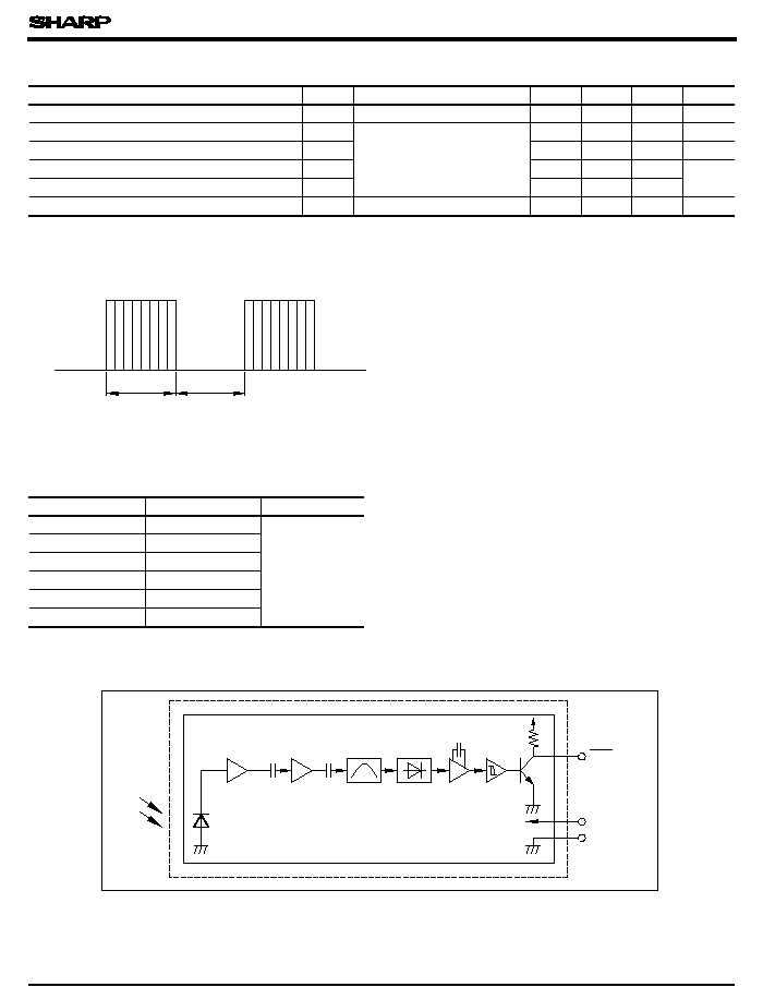
*3 The burst wave as shown in the following figure shall be transmitted by the transmitter shown in Fig. 1.
GP1U77R
GP1U770R
GP1U771R
GP1U772R
GP1U773R
GP1U777R
s
Internal Block Diagram
The value of f
O
is shown in a separate table.
Duty 50%
600
µ
s
600
µ
s
Conditions
No input light
*3
-
*4
40
*4 Diversified models with a different B.P.F frequency, as shown in a separate table, are also available.
Vout
Vcc
GND
B.P.F.
Limiter
Amp
Comparator
Integrator
Demodulator
GP1U77R Series
s
Performance
( 1) Linear reception distance characteristics
characteristcs in the attached list.
( 2) Sensitivity angle reception distance characteristics
( 3) Anti outer peripheral light reception distance characteristics
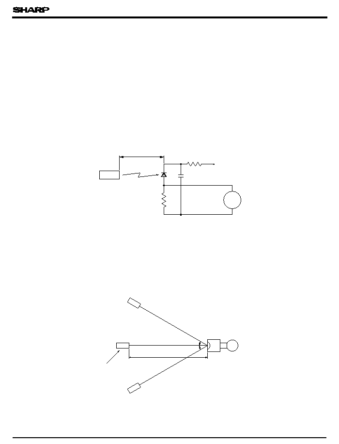
In the above figure, the transmitter should be set so that the output V out can be 40mV
PP
.
100 lx.
(E
V
is an illuminance by CIE standard light source A ( tungsten lamp ) .)
characteristics in the attached list.
electrical characteristics in the attached list.
20cm
10k
+
5V
10
µ
F
PD49PI
10k
Oscilloscope
Vout
Transmitter
Vout
Transmitter (GL521 used )
Duty 50
%
Center frequency (fo)
depends on the attached
model list.
Fig. 1. Transmitter
Fig. 2. Standard optical system
Reception distance
:
L
Light detector face
illuminance
:
Ee
vertical directions. )
Using the transmitter shown in Fig. 1, the output signal of the light detecting unit is good enough
to meet the following items in the standard optical system in Fig. 2.
in Fig. 2, the output signal shall meet the
in Fig. 2, the output signal shall meet the electrical
However, the
PD49PI
to be used here should be of the short-circuit current I
SC
= 2.6
µ
A at E
V
=
in Fig. 2, the output signal shall meet the electrical
When L= 0.2 to 6.5m, Ee < 10 lx and
= 0∞
When L = 0.2 to 4.5m, Ee < 10 lx and
<= 30∞
When L= 0.2 to 3m, Ee <= 300 lx and
= 0∞
(
indicates horizontal and

s
Precautions for Use
GP1U77R Series
( 2) Pay attention to a malfunction of the light detecting unit when the surface is stained with
( 3) The shield case shall be grounded on PWB pattern.
( 4) Do not apply unnecessary force to the terminals and case form outside.
( 5) Do not push the light detector surface ( photodiode ) from outside.
( 6) To avoid the electorstatic breakdown of IC, handle the unit under the condition of ground-
( 7) In case of adopting the infrared light detecting unit for the wireless remote control, use it
( 8) As for other general cautions, refer to the chapter " Precautions for Use" ( Page 78 to 93 ) .
characteristics and operating condition of light emitting device and the characteristics of
the light detecting unit.
dust and refuse. Care must be taken not to touch the light detector surface. If it should be
dirty, wipe off with soft cloth so as to prevent scratch. In case some solvents are required,
use metyl alcohol, ethyl alcohol or isoprophyl alcohol. Also, protect the light detecting unit
against flux and others.
ing with human body, soldering iron, etc.
in accordance with the transmission scheme and the signal format recommended in " Coun-
termeasures for malfunction prevention of home appliances with infrared remote control"
issued form Japan Association of Electrical Home Appliances ( AEHA ) in July 1987.
( 1) Use the light emitting unit ( remote control transmitter ) , in consideration of performance,