PC419K
PC419K
s
Features
1. Bi-directional linear output
2. High breakdown voltage
( V
BR
: 120V)
3. Low collector dark current
( I
d
4. High isolation voltage between input and
s
Applications
1. Board testers
2. Programmable controllers
3. Analog switch
s
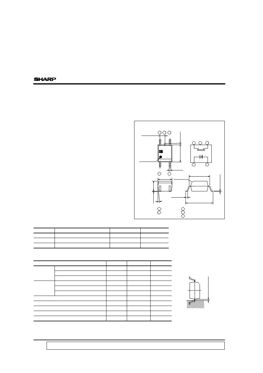
Package Specifications
Model No.
Package specifications
Diameter of reel
Tape width
370mm
12mm
178mm
12mm
-
-
PC419
Anode mark
Internal connection
diagram
6
į
Soldering area
s
Outline Dimensions
( Unit : mm )
Parameter
Symbol
Rating
Unit
Input
Forward current
I
F
50
mA
Reverse voltage
V
R
6
V
*1
Power dissipation
P
70
mW
Output
Output current
I
O
10
mA
Breakdown voltage
V
BR
120
V
*1
Power dissipation
P
O
100
mW
Total power dissipation
P
tot
120
mW
Isolation voltage
V
iso
V
rms
Operating temperature
T
opr
- 25 to + 100
įC
Storage temperature
T
stg
- 40 to + 125
įC
Soldering temperature
T
sol
260
įC
s
Absolute Maximun Ratings
(Ta = 25įC )
PC419K
PC419KT
PC419KZ
data books, etc. Contact SHARP in order to obtain the latest version of the device specification sheets before using any SHARP's device.
"
"
In the absence of confirmation by device specification sheets, SHARP takes no responsibility for any defects that occur in equipment using any of SHARP's devices, shown in catalogs,
mounting
6
5
4
1
3
6
5
4
1
3
1 Anode
3 Cathode
4 Source
5 NC
6 Drain
C0.4
(Imput side)
0.6MAX
0.2mm or more
Compact Surface Mounted,
Bi-directional Linear
Output Type Photocoupler
: MAX. 10nA )
*1
*2
*1 AC for 1 minute, 40 to 60% RH
output ( V
iso
: 3 750V
rms
)
4. Hybrid substrates which require high density
Taping package
( Net : 3 000pcs. )
Taping package
( Net : 750pcs. )
Sleeve package
( Net : 100pcs. )
*2 10 seconds or less, 0.2mm or more from the root of lead.
3 750
4.4
Ī
0.2
1.27
Ī
0.25
0.4
Ī
0.1
3.6
Ī
0.3
2.6
Ī
0.2
0.1
Ī
0.1
5.3
Ī
0.3
0.2
Ī
0.05
0.5
+
0.4
-
0.2
7.0
+
0.2
-
0.7
PC419K
s
Electro-optical Characteristics
( Ta = 25įC)
Parameter
Symbol
Conditions
MIN.
TYP.
MAX.
Unit
Input
Forward voltage
V
F
I
F
= 16mA
-
1.2
1.4
V
Reverse current
I
R
V
R
= 6V
-
-
10
Ķ
A
Terminal capacitance
C
t1
V = 0, f = 1kHz
-
50
250
pF
Output
Breakdown voltage
V
BR
I
46
= 100
Ķ
A, I
F
= 0
120
-
-
V
Collector dark current
I
d
V
46
= 100V, I
F
= 0
-
-
10
nA
R
OFF
V
46
F
= 0
10
10
-
-
Terminal capacitance
C
t2
V
46
= 0, f = 1MHz
-
-
25
pF
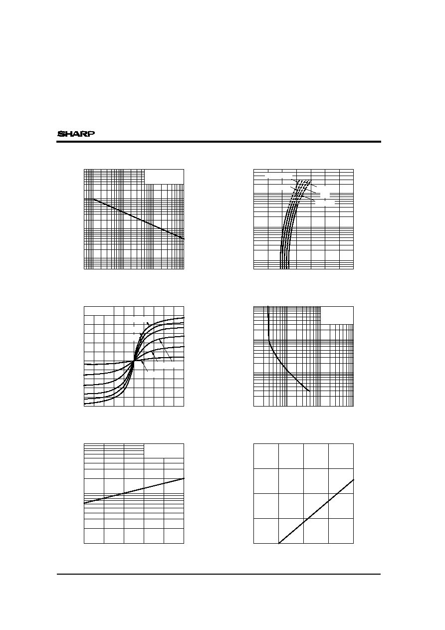
0
- 25
30
F
(
mA
)
0
25
50
75
100
125
40
50
60
20
10
Fig. 1 Forward Current vs.
Ambient Temperature
Ambient temperature T
a
(įC)
Ambient Temperature
0
100
- 25
50
0
25
50
75
100
125
Fig. 2 Power Dissipation vs.
Ambient temperature T
a
(įC)
Forward current I
*3
*3
*3
OFF-state resistance
*3
ON-state resistance
R
ON
I
F
= 16mA, I
46
= 100
Ķ
A
-
-
200
Isolation resistance
R
ISO
DC500V, 40 to 60% RH
5 x 10
10
10
11
-
Floating capacitance
Cf
V = 0, f = 1MHz
-
-
2.5
pF
Turn-on time
t
on
I
F
= 16mA, V
46
= 5V
R
L
= 50
-
-
65
Ķ
s
Turn-off time
t
off
-
-
65
Transfer
charac-
teristics
Power dissipation P
O
(
mW
)
*3 Applies to forward and reverse directions between terminals 4 and 6.
= 100V, I
PC419K
Duty ratio
5
5
10
20
100
50
200
500
2
10
- 2
5
2
10
- 1
5
2
5
Fig. 3 Peak Forward Current vs. Duty Ratio
Peak forward current I
FM
(
mA
)
Fig. 4 Forward Current vs.
Forward Voltage
1.0
0.8
0.6
0.4
0.2
0
- 0.2
- 0.4
- 0.6
- 0.8
200
100
0
- 100
- 200
Output voltage V
46
( mV )
16mA
14mA
2mA
6mA 10mA
Output current I
46
(
mA
)
Fig. 5 Output Current vs. Output Voltage
100
50
10
1
10
Forward Current
F
( mA )
10
5
2
1
0.5
0.2
100
75
50
25
0
- 25
Fig. 7 Relative ON-state Resistance vs.
Ambient Temperature
Ambient temperature T
a
(įC)
100
1
10
100
75
50
25
0
Fig. 8 Relative Collector Dark Current vs.
Ambient Temperature
Ambient temperature T
a
(įC)
Pulse width <=100
Ķ
s
Relative collector dark current
Forward current I
Fig. 6 ON-state Resistance vs.
ON-state resistance R
ON
(
)
V
46
= 100V
I
F
= 0
1
- 1.0
0.1
50įC
25įC
0įC
0
2
0.5
1.0
1.5
2.0
2.5
3.0
3.5
5
10
20
50
100
200
500
1
- 25įC
T
a
= 75įC
F
(
mA
)
Forward voltage V
F
(V)
Forward current I
Relative ON-state resistance
T
a
= 25įC
10
- 3
T
a
= 25įC
I
F
= 18mA
I
46
= 100
Ķ
A
T
a
= 25įC
I
46
= 100
Ķ
A
I
F
= 16mA
10000
5000
2000
1000
1000
10000
1000
10000
1000
Please refer to the chapter " Precautions for Use " .
100
q