 | –≠–ª–µ–∫—Ç—Ä–æ–Ω–Ω—ã–π –∫–æ–º–ø–æ–Ω–µ–Ω—Ç: PT4600F | –°–∫–∞—á–∞—Ç—å:  PDF PDF  ZIP ZIP |
(Ta = 25∞C)
Features
Applications
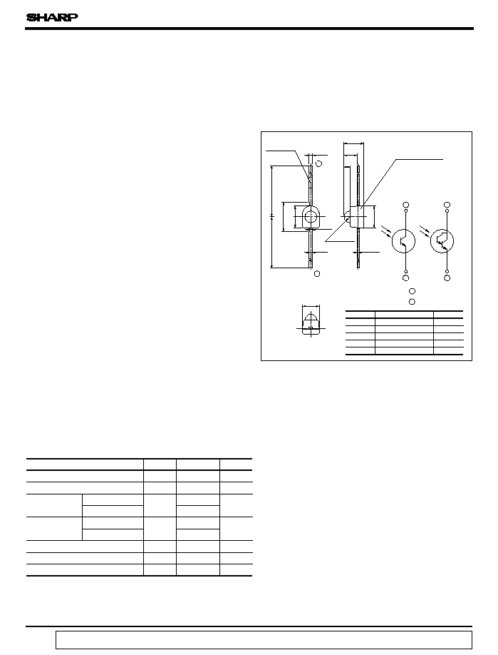
Outline Dimensions
(Unit : mm)
Absolute Maximum Ratings
Double Ended Mold Type
Phototransistors
1. Compact double ended mold package
PT4600/PT4600F/PT4610/
PF4610F/PF4650F
(Packaging area : 37% smaller than
PT480
)
Light sensitivity : 3 times as large as
PT460
series)
4. Taped model (2,000 pieces/reel) also available
1. Floppy disk drives
2. VCRs
3. Audio equipment
4. Video-movie kits
3. Darlington output type (
PT4610
), visible light cut-off
type (
PT4600F/4610F/4650F
), VCR tape end
detection type (
PT4650F
) available as standard
*
Tolerance :
±
0.2 mm
*1 For MAX. 3 seconds at the position of 2.5 mm from the resin edge
Parameter
Symbol
Rating
Unit
Collector-emitter voltage
V
CEO
35
V
Emitter-collector voltage
V
6
V
Collector
current
C
I
20
mA
50
Collector power
dissipation
P
C
50
mW
100
Operating temperature
T
opr
- 20 to + 85
∞C
Storage temperature
T
stg
- 40 to + 85
∞C
Soldering temperature
T
sol
260
∞C
*1
PT4600/PT4600F/PT4650F
PT4610/PT4610F
PT4610/PT4610F
PT4600/PT4600F/PT4650F
0.7
0.5
0.25
1.8
2.3
3.0
3.0
4.0
0.4
R0.8
0.8
PT4600
PT4600F
PT4650F
PT4610F
PT4610
1
2
2
2
1
1
MIN.
14.0
MIN.
15.5
*
2 Mark
2.7
MAX.
1 Emitter
2 Collector
*
1 Epoxy resin
PT4600/PT4600F/PT4610/PT4610F/PT4650F
2. Narrow beam angle
(Half intensity angle : ± 20∞
Model
*
1 Resin type
*
2
PT4600
Transparent
-
PT4600F
Black visible light cut-off
-
PT4610
Pale blue transparent
-
PT4610F
Black visible light cut-off
Red
PT4650F
Black visible light cut-off
Yellow
ECO
data books, etc. Contact SHARP in order to obtain the latest version of the device specification sheets before using any SHARP's device.
"
"
In the absence of confirmation by device specification sheets, SHARP takes no responsibility for any defects that occur in equipment using any of SHARP's devices, shown in catalogs,
s
s
s
s
(Ta = 25∞C)
Parameter
Symbol
Conditions
MIN.
TYP.
MAX.
Unit
Collector current
I
C
E
e
= 1mW/cm
2
V
CE
= 5V
-
mA
-
-
E
e
= 0.01mW/cm
2
V
CE
= 5V
-
-
Dark current
I
CEO
E
e
= 0, V
CE
= 20V
-
-
0.1
µ
A
E
e
= 0, V
CE
= 10V
-
-
1.0
V
CE(sat)
E
e
= 10mW/cm
2
I
C
= 0.5mA
-
0.2
0.4
V
E
e
= 1mW/cm
2
I
C
= 2.5mA
-
-
1.2
Collector-emitter breakdown voltage
BV
CEO
35
-
-
V
Emitter-collector breakdown voltage
BV
ECO
6
-
-
V
Peak sensitivity wavelength
p
-
-
-
nm
-
-
t
r
-
40
t
f
-
35
t
r
-
2 000
-
1 500
t
f
Half intensity angle
-
-
-
∞
800
860
10
8
400
300
Ambient temperature Ta (∞C)
Ambient temperature Ta (∞C)
PT4600
PT4600F
PT4650F
PT4610
PT4610F
PT4600/4600F/4650F
PT4600/PT4600F
PT4610/PT4610F
PT4650F
PT4610/PT4610F
PT4600/4610
PT4600F/4610F/4650F
PT4600/4600F/4650F
PT4610/4610F
V
CE
= 20V, I
C
= 1mA
V
CE
= 2V, I
C
= 10mA
*2
*2
I
C
= 0.1mA,
*2
E
e
= 0
I
C
= 0.01mA,
*2
E
e
= 0
R
L
= 1k
R
L
= 100
0.95
0.55
0.55
0.6
0.4
± 20
2.80
1.85
1.2
3.05
2.0
µ
s
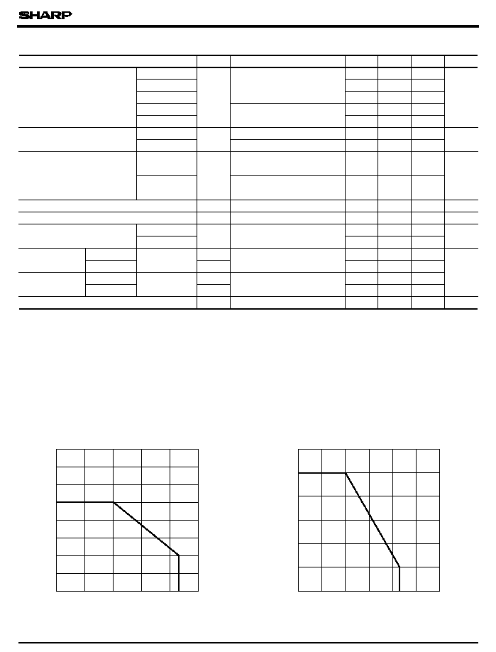
Fig. 1-a Collector Power Dissipation vs. Ambient
temperature(PT4600/4600F/4650F)
Fig. 1-b Collector Power Dissipation vs. Ambient
temperature
(PT4610/4610F)
Electro-optical Characteristics
Rise
Fall
Rise
Fall
Response time
Response time
Collector-emitter
saturation voltage
*2 E
e
: Irradiance by CIE standard light source
*2
*2
*2
*2
Collector power dissipation P
C
(mW)
Collector power dissipation P
C
(mW)
- 25
0
25
50
75
100
0
10
20
30
40
50
60
70
- 25
0
25
50
75
100
125
0
20
40
60
80
100
85
85
PT4600/PT4600F/PT4610/PT4610F/PT4650F
80
120
s
Ambient temperature Ta (∞C)
Ambient temperature Ta (∞C)
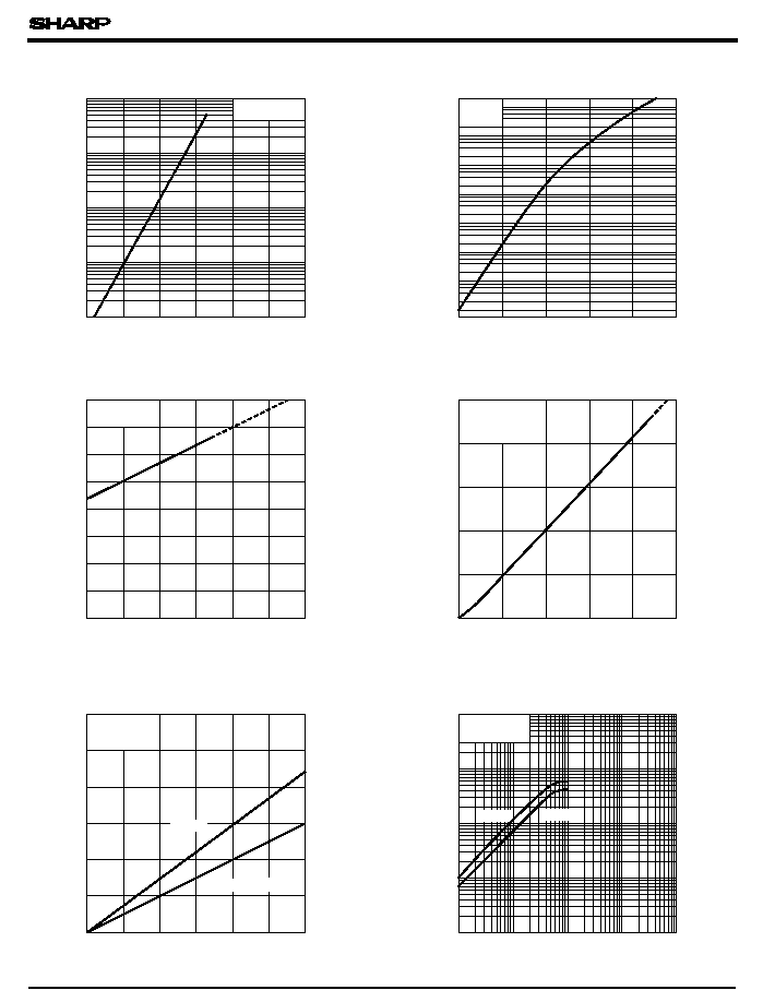
Fig. 3-a Relative Collector Current vs. Ambient
temperature (PT4600/4600F/4650F)
Ambient temperature Ta (∞C)
Ambient temperature Ta (∞C)
Dark current I
CEO
(A)
Dark current I
CEO
(A)
Fig. 4-a Collector Current vs. Irradiance
(PT4600/4600F/4650F)
Fig. 2-a Dark Current vs. Ambient temperature
(PT4600/4600F/4650F)
Fig. 2-b Dark Current vs. Ambient temperature
(PT4610/4610F)
Fig. 4-b Collector Current vs. Irradiance
(PT4610/4610F)
Fig. 3-b Relative Collector Current vs. Ambient
temperature
(PT4610/4610F)
50
75
- 25
50
0
25
75
100
100
125
150
10
-10
10
-11
10
- 9
5
- 25
5
5
25
0
50
10
- 6
10
- 7
10
- 8
10
- 4
10
- 5
5
5
5
5
5
100
75
0
25
50
75
100
125
10
- 6
10
- 7
10
- 8
10
- 9
10
- 10
0
25
50
75
100
125
150
0
20
40
60
80
100
120
140
160
0
2.5
5.0
7.5
10
12.5
15.0
0.1
1
10
1.0
10
100
0.01
100
0.1
V
CE
= 5V
= 25∞C
175
V
CE
= 20V
V
CE
= 10V
V
CE
= 5V
2
V
CE
= 10V
V
CE
= 5V
= 25∞C
150
Ev
Ee = 1mW/cm
Ta
Ta
PT4610
PT4610F
30
25
20
15
10
5
0
PT4600F/4650F
PT4600
PT4600/PT4600F/PT4610/PT4610F/PT4650F
Relative collector current (%)
Relative collector current (%)
Collector current I
C
(mA)
Collector current I
C
(mA)
= 2 lx
Irradiance E
e
(mA/cm
2
)
Irradiance E
e
(mW/cm
2
)
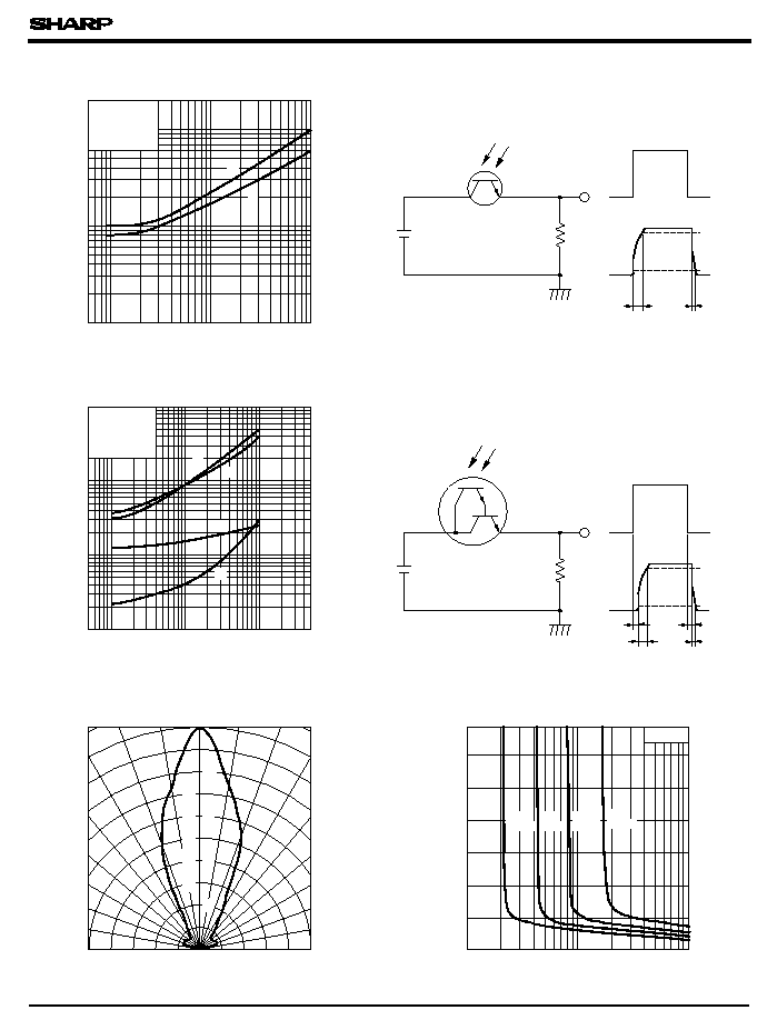
Fig. 7-a Response Time vs. Load Resistance
(PT4600/4600F/4650F)
Response time t
r
,t
f
(
µ
s)
Load resistance R
L
(k
)
Fig. 8 Radiation Diagram
Test Circuit for Response Time
Test Circuit for Response Time
Collector-emitter saturation voltage V
CE(sat)
(V)
(PT4600/4600F/4650F)
Fig. 7-b Response Time vs. Load Resistance
(PT4610/4610F)
(PT4610/4610F)
Fig. 9-a Collector-emitter Saturation Voltage
vs. Irradiance
(PT4600)
PT4600/PT4600F/PT4610/PT4610F/PT4650F
Angular displacement
5
1
2
500
50
10
20
100 200
5000
1000
V
CE
= 2V
I
C
= 10mA
= 25∞C
= 25∞C
I
C
= 1mA
V
CE
= 20V
5
50
5
10
20
200
100
500
1000
2
1
10
20
100
50
t
f
t
d
t
s
t
r
2
1
5
10
50
20
100
t
r
t
f
t
r
t
d
10
%
t
f
t
s
t
r
R
L
R
L
90
%
t
f
10
%
90
%
20
100
40
60
80
- 10
- 20
0
- 90
- 80
- 70
- 60
- 50
- 40
- 30
90
80
70
60
50
40
30
0
0
T
a
Vcc
Vcc
T
a
Output Input
Output
Output Input
Output
10
20
1.2
1
0.8
0.6
0.4
0.2
1.4
0.1
1
0.5
2
5
0.2
10
T
a
= 25∞C
Ic =
2.0mA
Ic =
Ic =
Ic =
0.25mA 0.5mA 1.0mA
Response time (
µ
s)
Load resistance R
L
(
)
Irradiance E
e
(mW/cm )
2
50
50
Relative sensitivity (%)
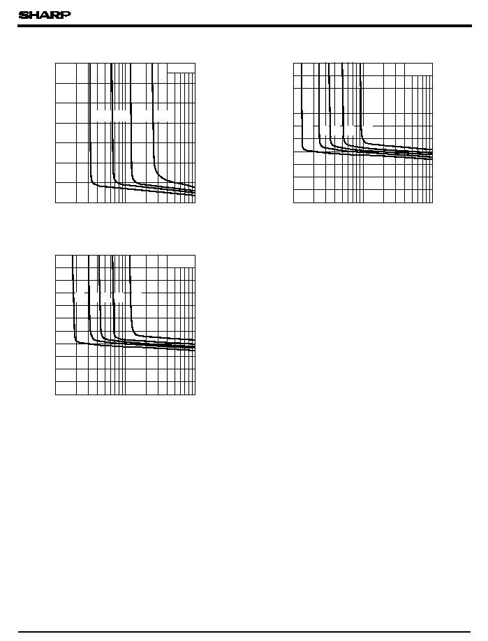
Fig. 9-b Collector-emitter Saturation Voltage
vs. Irradiance(PT4600F/PT4650F)
Collector-emitter saturation voltage V
CE(sat)
(V)
Collector-emitter saturation voltage V
CE(sat)
(V)
Collector-emitter saturation voltage V
CE(sat)
(V)
Fig. 9-c Collector-emitter Saturation Voltage
vs. Irradiance
(PT4610)
Fig. 9-d Collector-emitter Saturation Voltage
vs. Irradiance (PT4610F)
Please refer to the chapter "Precautions for Use". (Page 78 to 93)
10
0.01
0.1
1
0
2mA
5mA
10mA
0.4
0.6
0.8
1
1.2
1.4
1
0.2
2
0.5
5
Ta = 25∞C
Ta = 25∞C
2.2
2
1.8
1.6
1.4
1.2
1.
08
0.6
0.4
0.2
Ic =
1mA
Ic = Ic =
Ic =
3mA
Ic =
0.02
0.05
0.2
0.5
0.01
0.1
1
0
2mA
5mA
10mA
Ta = 25∞C
2.2
2
1.8
1.6
1.4
1.2
1.
08
0.6
0.4
0.2
Ic =
1mA
Ic= Ic =
Ic =
3mA
Ic =
0.02
0.05
0.2
0.5
PT4600/PT4600F/PT4610/PT4610F/PT4650F
0.1
0.2
0
Ic =
Ic =
Ic =
Ic =
0.25mA 0.5mA 1.0mA
2.0mA
Irradiance E
e
(mW/cm
2
)
Irradiance E
e
(mW/cm
2
)
Irradiance E
e
(mW/cm
2
)
q