
1
TGoddard/SP333/9617R0
SP333 RS-232/AppleTalk Programmable Transceiver
© Copyright 2000 Sipex Corporation
SP333
+5V Only RS-232/AppleTalkTM Programmable Transceiver
s
+5V Only, Single Supply Operation
s
Low Power Shutdown
s
28-Pin SOIC Packaging
s
3 Drivers, 5 Receivers ≠ RS-232
s
Complete AppleTalkTM Interface
s
High Data Rates
10Mbps Differential Transceivers
460kbps Single-Ended Transceivers
DESCRIPTION...
The SP333 is a monolithic device that supports both MacintoshTM and PC serial interfaces.
RS-232 mode offers three (3) RS-232 drivers and five (5) RS-232 receivers. Mac mode
includes a differential driver and a single-ended inverting driver. Receivers in Mac mode
include one differential receiver, one non-inverting single-ended receiver and one inverting
single-ended receiver. An on-chip charge pump allows +5V-only operation, and a low power
Shutdown mode makes the SP333 ideal for battery powered applications. The interface mode
can be changed at any time by a mode select pin.
+5V
5
0V
V
CC
25
9
12
10
0.1
µ
F
0.1
µ
F
14
26
11
13
0.1
µ
F
0.1
µ
F
C2-
C2+
V+
V-
Shutdown
RS-232/MacMode
TI1
TX1
27
6
T1
TI2
TX2
28
7
T2
TI3
TX3
1
4
T3
RX1
RI1
19
15
R1
RX2
RI2
20
16
R2
RX3
RI3
21
17
R3
RX4
RI4
22
18
R4
RX5
RI5
23
24
R5
RXEN
GND
3
8
+5V
5
+5V
V
CC
25
9
12
10
0.1
µ
F
0.1
µ
F
14
26
11
13
0.1
µ
F
0.1
µ
F
C2-
C2+
V+
V-
Shutdown
RS-232/MacMode
TI1
TX1
27
6
T1
TXEN
TX2
2
7
TI3
TX3
1
4
T3
RX1
19
R1
RI2 16
R3
RX3
RI3
21
17
RX5
RI5
23
24
R5
GND
3
8
RI1 15
PC Mode
Mac Mode
RXEN
SP333
SP333
Æ

2
TGoddard/SP333/9617R0
SP333 RS-232/AppleTalk Programmable Transceiver
© Copyright 2000 Sipex Corporation
ABSOLUTE MAXIMUM RATINGS
These are stress ratings only and functional operation of the device at
these ratings or any other above those indicated in the operation sections
of the specifications below is not implied. Exposure to absolute maximum
rating conditions for extended periods of time may affect reliability.
V
CC
...................................................................................................+12V
Input Voltages
Logic........................................................-0.3V to (V
CC
+0.5V)
Drivers..................................................-0.3V to (V
CC
+0.5V)
Receivers..................................................................
±
15V
Driver Outputs......................................................................................
±
14V
Storage Temperature..................................................-65∞C to +150∞C
Power Dissipation..........................................................................1000mW
SPECIFICATIONS
T
MIN
to T
MAX
and V
CC
= 5V
±
5% unless otherwise noted.
PARAMETER
MIN.
TYP.
MAX.
UNITS
CONDITIONS
MAC Mode (pin 25 = +5V)
Differential Driver
High Level Output Voltage
+3.6
Volts
I
OH
= 8mA
Low Level Output Voltage
-3.6
Volts
I
OH
= ≠8mA
Differential Output, Load
±
5V
Volts
R
L
= 450
(TX outputs to GND)
Differential Output, No Load
±
10
Volts
R
L
=
Driver Short Circuit Current
±
40
500
mA
≠7V
V
O
+7V; V
IN LOW
0.8V or
V
IN HIGH
2.0V
Output Leakage Current
±
100
µ
A
≠7V
V
O
+7V; TxEN = V
CC
Input High Voltage
2.0
Volts
Applies to differential driver inputs
Input Low Voltage
0.8
Volts
Applies to differential driver inputs
Input Current
±
20
µ
A
V
IN
= 0V to V
CC
Transition Time
30
ns
R
L
= 450
, C
L
= 50pF; Rise/Fall
10% ≠ 90%
Propagation Delay
t
PHL
100
ns
R
L
= 450
, C
L
= 50pF
t
PLH
100
ns
R
L
= 450
, C
L
= 50pF
Data Rate
10
Mbps
R
L
= 450
, C
L
= 50pF
Single-Ended Inverting Driver
High Level Output Voltage
+3.6
+6.0
Volts
R
L
= 450
to GND; V
IN LOW
0.8V or
V
IN HIGH
2.0V
Low Level Output Voltage
≠6.0
≠3.6
Volts
R
L
= 450
to GND; V
IN LOW
0.8V or
V
IN HIGH
2.0V
Driver Open Circuit Voltage
±
10
Volts
R
L
=
Driver Short Circuit Current
±
40
mA
≠7V
V
O
+7V; Infinite duration
Input High Voltage
2.0
Volts
Applies to single-ended driver inputs
Input Low Voltage
0.8
Volts
Applies to single-ended driver inputs
Input Current
±
20
µ
A
V
IN
= 0V to V
CC
Transition Time
30
ns
R
L
= 450
, C
L
= 50pF; Rise/Fall
10% ≠ 90%
Propagation Delay
t
PHL
100
ns
R
L
= 450
, C
L
= 50pF
t
PLH
100
ns
R
L
= 450
, C
L
= 50pF
Data Rate
10
Mbps
R
L
= 450
, C
L
= 50pF
Differential Receiver
Differential Input Threshold
-0.2
+0.2
Volts
-7V
V
CM
+7V
Input Hysteresis
70
mV
V
CM
=0V
Input Resistance
12
k
-7V
V
CM
+7V
Output Voltage High
3.5
Volts
I
SOURCE
= ≠4mA
Output Voltage Low
0.4
Volts
I
SINK
= +4mA
Short Circuit Current
85
mA
0V
V
OUT
V
CC

3
TGoddard/SP333/9617R0
SP333 RS-232/AppleTalk Programmable Transceiver
© Copyright 2000 Sipex Corporation
SPECIFICATIONS (CONTINUED)
T
MIN
to T
MAX
and V
CC
= 5V
±
5% unless otherwise noted.
PARAMETER
MIN.
TYP.
MAX.
UNITS
CONDITIONS
Differential Receiver
Propagation Delay
t
PHL
100
ns
R
L
= 450
, C
L
= 50pF
t
PLH
100
ns
R
L
= 450
, C
L
= 50pF
Data Rate
10
Mbps
R
L
= 450
, C
L
= 50pF
Single-Ended Inverting Receiver
Input Voltage Range
≠15
+15
Volts
Input Threshold Low
0.8
1.2
Volts
Input Threshold High
1.7
3.0
Volts
Hysteresis
200
500
1000
mV
Input Impedance
3
5
7
k
Output Voltage High
3.5
Volts
I
SOURCE
= ≠4mA
Output Voltage Low
0.4
Volts
I
SINK
= +4mA
Propagation Delay
t
PHL
100
ns
t
PLH
100
ns
Data Rate
10
Mbps
Single-Ended Non-Inverting Receiver
Input Voltage Range
≠7
+7
Volts
Input Threshold Low
-0.2
Volts
Input Threshold High
+0.2
Volts
Hysteresis
70
mV
Input Impedance
12
15
k
Output Voltage High
3.5
Volts
I
SOURCE
= ≠4mA
Output Voltage Low
0.4
Volts
I
SINK
= +4mA
Propagation Delay
t
PHL
100
ns
t
PLH
100
ns
Data Rate
10
Mbps
PC Mode (pin 25 = GND)
RS-232 Driver
TTL Input Levels
V
IL
0.8
Volts
Applies to transmitter inputs
V
IH
2.0
Volts
Applies to transmitter inputs
High Level Voltage Output
+5.0
+15.0
Volts
R
L
= 3k
to Gnd
Low Level Voltage Output
-15.0
-5.0
Volts
R
L
= 3k
to Gnd
Open Circuit Output
±
15
Volts
R
L
=
Short Circuit Current
±
100
mA
V
OUT
= Gnd
Power Off Impedance
300
Ohms
V
CC
=0V; V
OUT
=
±
2V
Slew Rate
60
V/
µ
s
R
L
=3k
, C
L
=50pF; From +3V
to -3V or -3V to +3V
Transition Time
1.56
µ
s
Rise/fall time, between +3V & ≠3V
; R
L
=3k
, C
L
=2500pF
Propagation Delay
t
PHL
1.5
µ
s
R
L
=3k
, C
L
=1000pF; From 1.5V
of T
IN
to 50% of V
OUT
t
PLH
1.3
µ
s
R
L
=3k
, C
L
=1000pF; From 1.5V
of T
IN
to 50% of V
OUT
Data Rate
460
600
kbps
R
L
=3k
, C
L
=1000pF
RS-232 Receiver
TTL Output Levels
V
OL
0.4
Volts
I
SINK
= 4mA
V
OH
2.4
I
SOURCE
= -4mA
Receiver Input
High Threshold
1.7
3.0
Volts
4
TGoddard/SP333/9617R0
SP333 RS-232/AppleTalk Programmable Transceiver
© Copyright 2000 Sipex Corporation
SPECIFICATIONS (CONTINUED)
T
MIN
to T
MAX
and V
CC
= 5V
±
5% unless otherwise noted.
PARAMETER
MIN.
TYP.
MAX.
UNITS
CONDITIONS
RS-232 Receiver
Low Threshold
0.8
1.2
Volts
Input Voltage Range
-15
+15
Volts
Input Impedance
3
5
7
kOhms
V
IN
=
±
15V
Hysteresis
0.2
0.5
1.0
Volts
V
CC
=+5V
Transmission Rate
10
Mbps
Propagation Delay
t
PHL
100
600
ns
From 50% of V
IN
to 1.5V of R
OUT
t
PLH
100
600
ns
From 50% of V
IN
to 1.5V of R
OUT
Data Rate
460
600
kbps
POWER REQUIREMENTS
No Load Supply Current
15
25
mA
No load; V
CC
=5.0V; T
A
=25∞C
Shutdown Supply Current
75
µ
A
T
A
=25∞C, V
CC
=5.0V
AC PARAMETERS
Differential Mode
t
PZL
; Enable to Output low
200
1000
ns
C
L
=100pF, Figures 2 & 4, S
2
closed
t
PZH
; Enable to Output high
200
1000
ns
C
L
=100pF, Figures 2 & 4, S
1
closed
t
PLZ
; Disable from Output low
200
1000
ns
C
L
=15pF, Figures 2 & 4, S
2
closed
t
PHZ
; Disable from Output high
200
1000
ns
C
L
=15pF, Figures 2 & 4, S
1
closed
Receiver Delay Time from Enable Mode to Tri-state Mode
Single-Ended Mode
t
PZL
; Enable to Output low
200
1000
ns
C
RL
=15pF, Figures 1 & 6, S
1
closed
t
PZH
; Enable to Output high
200
1000
ns
C
RL
=15pF, Figures 1 & 6, S
2
closed
t
PLZ
; Disable from Output low
200
1000
ns
C
RL
=15pF, Figures 1 & 6, S
1
closed
t
PHZ
; Disable from Output high
200
1000
ns
C
RL
=15pF, Figures 1 & 6, S
2
closed
Differential Mode
t
PZL
; Enable to Output low
200
1000
ns
C
RL
=15pF, Figures 1 & 6, S
1
closed
t
PZH
; Enable to Output high
200
1000
ns
C
RL
=15pF, Figures 1 & 6, S
2
closed
t
PLZ
; Disable from Output low
200
1000
ns
C
RL
=15pF, Figures 1 & 6, S
1
closed
t
PHZ
; Disable from Output high
200
1000
ns
C
RL
=15pF, Figures 1 & 6, S
2
closed
Notes:
1.
Measured from 2.5V of R
IN
to 2.5V of R
OUT
.
2.
Measured from one≠half of R
IN
to 2.5V of R
OUT
.
3.
Measured from 1.5V of T
IN
to one≠half of T
OUT
.
4.
Measured from 2.5V of R
O
to 0V of A and B.
500
C
L
Output
Under
Test
S
1
S
2
V
CC
1K
1K
C
RL
Receiver
Output
S
1
S
2
Test Point
V
CC
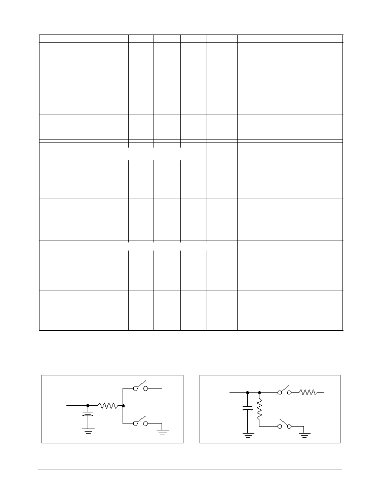
Figure 2. Receiver Timing Test Load
C i r c u i t
Figure 1. Driver Timing Test Load
C i r c u i t

5
TGoddard/SP333/9617R0
SP333 RS-232/AppleTalk Programmable Transceiver
© Copyright 2000 Sipex Corporation
+3V
0V
DRIVER INPUT
TX
2
TX
1
DRIVER
OUTPUT
V
O
+
DIFFERENTIAL
OUTPUT
TX
1
≠ TX
2
0V
V
O
≠
t
SKEW
t
SKEW
1.5V
1.5V
t
PLH
t
R
t
F
f = 1MHz; t
R
< 10ns; t
F
< 10ns
V
O
1/2V
O
1/2V
O
t
PHL
V
OH
V
OL
RX
1.5V
1.5V
t
PHL
f = 1MHz; t
R
< 10ns; t
F
< 10ns
OUTPUT
V
0D2
+
V
0D2
≠
RI
1
≠RI
2
0V
0V
t
PLH
INPUT
+3V
0V
TXEN
5V
V
OL
0V
1.5V
1.5V
t
ZL
t
ZH
f = 1MHz; t
R
< 10ns; t
F
< 10ns
V
OH
TX
x
2.3V
2.3V
t
LZ
t
HZ
0.5V
0.5V
Output normally LOW
Output normally HIGH
TX
x
Figure 4. Driver Enable and Disable Times
Figure 5. Receiver Propagation Delays
Figure 3. Driver Propagation Delays