 | –≠–ª–µ–∫—Ç—Ä–æ–Ω–Ω—ã–π –∫–æ–º–ø–æ–Ω–µ–Ω—Ç: SP1481E | –°–∫–∞—á–∞—Ç—å:  PDF PDF  ZIP ZIP |

1
Rev:B Date: 02/26/04
SP1481E Low Power Half-Duplex RS485 Transceivers
© Copyright 2004 Sipex Corporation
SP1481E
+5V supply
Low Power BiCMOS
Driver/Receiver Enable for Multi-Drop
configurations
Low Power Shutdown Mode (1
µ
A
Typical)
Available in 8 Pin NSOIC or PDIP
packages (Standard 75176 pinout)
Enhanced ESD Specifications:
+15KV Human Body Model
+15KV IEC1000-4-2 Air Discharge
+8KV IEC1000-4-2 Contact Discharge
±
15kV Enhanced Low Power Half-Duplex
RS-485 Transceivers
Æ
PRELIMINARY
The SP1481E is a half-duplex transceiver that meets the specifications of RS-485 and RS-
422 serial protocols with enhanced ESD performance. The ESD tolerance has been improved
on this device to over +15KV for both Human Body Model and IEC1000-4-2 Air Discharge
Method. This device is pin-to-pin compatible with Sipex's SP485 and SP481 devices as well
as popular industry standards. As with the original version, the SP1481E features Sipex's
BiCMOS design allowing low power operation without sacrificing performance. The SP1481E
meets the requirements of the RS-485 and RS-422 protocols up to 20Mbps under load.
DESCRIPTION
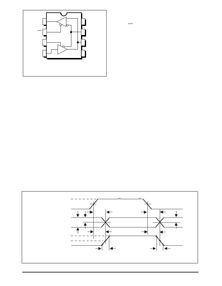
R
D
RO 1
RE 2
DE 3
DI 4
8 Vcc
7 B
6 A
5 GND
SP1481E
BLOCK DIAGRAM
1
2
3
4
5
6
7
8
RO
SP1481E
8 Pin - nSOIC
DE
RE
B
VCC
A
DI
GND

Rev:B Date: 02/26/04
SP1481E Low Power Half-Duplex RS485 Transceivers
© Copyright 2004 Sipex Corporation
2
ABSOLUTE MAXIMUM RATINGS
These are stress ratings only and functional operation of the device at
these ratings or any other above those indicated in the operation sections
of the specifications below is not implied. Exposure to absolute maximum
rating conditions for extended periods of time may affect reliability.
V
CC
............................................................................................................+7V
Input Voltages
Logic........................................................-0.3V to (V
CC
+0.5V)
Drivers..................................................-0.3V to (V
CC
+0.5V)
Receivers.................................................................
±
15V
T
MIN
to T
MAX
and V
CC
= 5V
±
5% unless otherwise noted.
PARAMETERS
MIN.
TYP.
MAX.
UNITS
CONDITIONS
SP1481E DRIVER
DC Characteristics
Differential Output Voltage
3.5
V
CC
Volts
Unloaded; R =
;
see Figure 1
Differential Output Voltage
2
V
CC
Volts
with load; R = 50
; (RS-422);
see Figure 1
Differential Output Voltage
1.5
V
CC
Volts
with load; R = 27
; (RS-485);
see Figure 1
Change in Magnitude of Driver
Differential Output Voltage for
Complimentary States
0.2
Volts
R = 27
or R = 50
;
see Figure 1
Driver Common-Mode
Output Voltage
3
Volts
R = 27
or R = 50
;
see Figure 1
Input High Voltage
2.0
Volts
Applies to DE, DI, RE
Input Low Voltage
0.8
Volts
Applies to DE, DI, RE
Input Current
±
10
µ
A
Applies to DE, DI, RE
Driver Short-Circuit Current
V
OUT
= HIGH
±
250
mA
-7V
V
O
+12V
V
OUT
= LOW
±
250
mA
-7V
V
O
+12V
SP1481E DRIVER
AC Characteristics
Maximum Data Rate
20
Mbps
RE = 5V, DE = 5V; R
DIFF
= 54
,
C
L1
= C
L2
= 100pF
Driver Input to Output
10
30
40
ns
t
PLH
; R
DIFF
= 54
, C
L1
= C
L2
= 100pF;
see Figures 3 and 5
10
ns t
PHL
; R
DIFF
= 54
, C
LI
= C
L2
= 100pF;
Driver Skew
3
ns
see Figures 3 and 5,
t
SKEW
= | t
DPLH
- t
DPHL
|
Driver Rise or Fall Time
8
20
ns
From 10% to 90%; R
DIFF
= 54
,
C
L1
= C
L2
= 100pF;
see Figures 3 & 6
Driver Enable to Output High
40
70
ns
C
L
= 100pF;
see Figures 4 & 6; S
2
closed
Driver Enable to Output Low
40
70
ns
C
L
= 100pF;
see Figures 4 & 6; S
1
closed
Driver Disable Time from Low
40
70
ns
C
L
= 100pF;
see Figures 4 & 6; S
1
closed
Driver Disable Time from High
40
70
ns
C
L
= 100pF;
see Figures 4 & 6; S
2
closed
Output Voltages
Logic........................................................-0.3V to (V
CC
+0.5V)
Drivers......................................................................
±
15V
Receivers............................................-0.3V to (V
CC
+0.5V)
Storage Temperature.......................................................-65∞C to +150∞C
Power Dissipation per Package
8-pin NSOIC (derate 6.60mW/
o
C above +70
o
C)...........................550mW
8-pin PDIP (derate 11.8mW/
o
C above +70
o
C)............................1000mW
ELECTRICAL CHARACTERISTICS

3
Rev:B Date: 02/26/04
SP1481E Low Power Half-Duplex RS485 Transceivers
© Copyright 2004 Sipex Corporation
T
MIN
to T
MAX
and V
CC
= 5V
±
5% unless otherwise noted.
PARAMETERS
MIN.
TYP.
MAX.
UNITS
CONDITIONS
SP1481E RECEIVER
DC Characteristics
Differential Input Threshold
-0.2
+0.2
Volts
-7V
V
CM
+12V
Differential Input Threshold
-0.4
+0.4
Volts
-7V
V
CM
+12V
(SP1485EMN ONLY)
Input Hysteresis
20
mV
V
CM
= 0V
Output Voltage High
3.5
Volts
I
O
= -4mA, V
ID
= +200mV
Output Voltage Low
0.4
Volts
I
O
= +4mA, V
ID
= -200mV
Three-State (High Impedance)
Output Current
±
1
µ
A
0.4V
V
O
2.4V; RE = 5V
Input Resistance
12
15
k
-7V
V
CM
+12V
Input Current (A, B); V
IN
= 12V
+1.0
mA
DE = 0V, V
CC
= 0V or 5.25V, V
IN
= 12V
Input Current (A, B); V
IN
= -7V
-0.8
mA
DE = 0V, V
CC
= 0V or 5.25V, V
IN
= -7V
Short-Circuit Current
7
95
mA
0V
V
O
V
CC
SP1481E RECEIVER
AC Characteristics
Maximum Data Rate
20
Mbps
RE = 0V, DE = 0V
Receiver Input to Output
15
40
50
ns
t
PLH
; R
DIFF
= 54
,
C
L1
= C
L2
=
100pF;
Figures 3 & 7
15
ns t
PHL
; R
DIFF
= 54
, C
LI
= C
L2
= 100pF
Diff. Receiver Skew It
PLH
-t
PHL
I
5
10
ns
R
DIFF
= 54
; C
L1
= C
L2
= 100pF;
Figures 3 & 7
Receiver Enable to
Output Low
45
70
ns
C
RL
= 15pF;
Figures 2 & 8; S
1
closed
Receiver Enable to
Output High
45
70
ns
C
RL
= 15pF;
Figures 2 & 8; S
2
closed
Receiver Disable from Low
45
70
ns
C
RL
= 15pF;
Figures 2 & 8; S
1
closed
Receiver Disable from High
45
70
ns
C
RL
= 15pF;
Figures 2 & 8; S
2
closed
SP1481E
Shutdown Timing
Time to Shutdown
50
200
600
ns
RE = 5V, DE = 0V
Driver Enable from Shutdown
to Output High
40
100
ns
C
L
= 100pF;
See Figures 4 & 6; S
2
closed
Driver Enable from Shutdown
to Output Low
40
100
ns
C
L
= 100pF;
See Figures 4 & 6; S
1
closed
Receiver Enable from
Shutdown to Output High
300
1000
ns
C
L
= 15pF;
See Figures 2 & 8; S
2
closed
Receiver Enable from
Shutdown to Output Low
300
1000
ns
C
L
= 15pF;
See Figures 2 & 8; S
1
closed
POWER REQUIREMENTS
Supply Voltage
+4.75
+5.25
Volts
Supply Current
SP1481E
No Load
900
µ
A
RE, DI = 0V or V
CC
; DE = V
CC
600
µ
A
RE = 0V, DI = 0V or 5V; DE = 0V
SHUTDOWN 10
µ
A
RE = 5V, DE = 0V
ENVIRONMENTAL
AND MECHANICAL
Operating Temperature
Commercial (_C_)
0
+70
∞
C
Industrial (_E_)
-40
+85
∞
C
(_M_)
-40
+125
∞
C
Storage Temperature
-65
+150
∞
C
Package
Plastic DIP (_P)
NSOIC (_N)
SPECIFICATIONS (continued)
Rev:B Date: 02/26/04
SP1481E Low Power Half-Duplex RS485 Transceivers
© Copyright 2004 Sipex Corporation
4
PIN FUNCTION
Pin 1 ≠ RO ≠ Receiver Output.
Pin 2 ≠ RE ≠ Receiver Output Enable Active LOW.
Pin 3 ≠ DE ≠ Driver Output Enable Active HIGH.
Pin 4 ≠ DI ≠ Driver Input.
Pin 5 ≠ GND ≠ Ground Connection.
Pin 6 ≠ A ≠ Driver Output/Receiver Input
Non-inverting.
Pin 7 ≠ B ≠ Driver Output/Receiver Input Inverting.
Pin 8 ≠ Vcc ≠ Positive Supply 4.75V<Vcc< 5.25V.
SP1485E
Pinout (Top View)
RO 1
RE 2
DE 3
DI 4
8 V
CC
7 B
6 A
5 GND
D
R
SP485
Top View
Figure 5. Driver Propagation Delays
+3V
0V
DI
B
A
DRIVER
OUTPUT
V
O
+
DIFFERENTIAL
OUTPUT
V
A
≠ V
B
0V
V
O
≠
1.5V
1.5V
t
PLH
t
R
t
F
f = 1MHz; t
R
< 1.0ns; t
F
< 1.0ns
V
O
1/2V
O
1/2V
O
t
PHL
t
DPLH
t
DPHL
t
SKEW =
|
t
DPLH -
t
DPHL
|
5
Rev:B Date: 02/26/04
SP1481E Low Power Half-Duplex RS485 Transceivers
© Copyright 2004 Sipex Corporation
INPUTS
OUTPUTS
LINE
RE
DE
DI CONDITION
B
A
X
1
1
No Fault
0
1
X
1
0
No Fault
1
0
X
0
X
X
Z
Z
X
1
X
Fault
Z
Z
INPUTS
OUTPUTS
RE
DE
A - B
R
0
0
+0.2V
1
0
0
-0.2V
0
0
0
Inputs Open
1
1
0
X
Z
Table 1. Transmit Function Truth Table
Table 2. Receive Function Truth Table
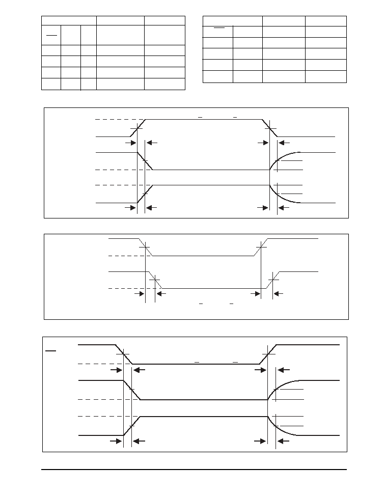
+3V
0V
DE
5V
V
OL
A, B
0V
1.5V
1.5V
t
ZL
t
ZH
f = 1MHz; t
R
< 1.0ns; t
F
< 1.0ns
V
OH
A, B
2.3V
2.3V
t
LZ
t
HZ
0.5V
0.5V
Output normally LOW
Output normally HIGH
+3V
0V
RE
5V
R
0V
1.5V
1.5V
t
ZL
t
ZH
f = 1MHz; t
R
< 1.0ns; t
F
< 1.0ns
R
1.5V
1.5V
t
LZ
t
HZ
0.5V
0.5V
Output normally LOW
Output normally HIGH
V
IL
V
IH
Figure 8. Receiver Enable and Disable Times
Figure 7. Receiver Propagation Delays
Figure 6. Driver Enable and Disable Times
V
OH
V
OL
R
1.5V
1.5V
t
PHL
f = 1MHz; t
R
< 1.0ns; t
F
< 1.0ns
OUTPUT
V
0D2
+
V
0D2
≠
A ≠ B
0V
0V
t
PLH
INPUT
t
SKEW =
|
t
PHL -
t
PLH
|