 | –≠–Ľ–Ķ–ļ—ā—Ä–ĺ–Ĺ–Ĺ—č–Ļ –ļ–ĺ–ľ–Ņ–ĺ–Ĺ–Ķ–Ĺ—ā: SP4424 | –°–ļ–į—á–į—ā—Ć:  PDF PDF  ZIP ZIP |

SP4424DS/16
SP4424 Electroluminescent Lamp Driver
© Copyright 2000 Sipex Corporation
1
DESCRIPTION
The SP4424 is a high voltage output DC-AC converter that can operate from a single battery
supply voltage as low as 2.2V. The SP4424 is capable of supplying up to 220 V
PP
signals,
making it ideal for driving electroluminescent lamps. The device features 5
Ķ
A (maximum)
standby current, for use in low power portable products. An inductor is used to generate high
voltage pulses, and two external capacitors are used to select the inductor and the lamp
oscillator frequencies. The SP4424 is offered in both an 8-pin narrow SOIC and 8-pin micro
SOIC packages. For delivery in die form, please consult the factory.
s
DC to AC Inverter for EL Backlit
Display Panels
s
2.2V - 5.0V Battery Operation
s
Dual Oscillator Operation for
Application Flexibility
s
Low Current Standby Mode
APPLICATIONS
s
PDAs
s
Cellular Phones
s
Remote Controls
s
Hand Held Computers
SP4424 Block Diagram
SP4424
Electroluminescent Lamp Driver
Dual Oscillators
HON
V
DD
C
LAMP
V
SS
COIL
EL2
EL1
SP4424
8
7
4
3
2
1
5
6
C
COIL
ģ

SP4424DS/16
SP4424 Electroluminescent Lamp Driver
© Copyright 2000 Sipex Corporation
2
SPECIFICATIONS
(T= 25
į
C; V
DD
=3.0V; Lamp Load = 55nF; Coil = 5mH at 18 Ohms; Coil OSC = 220pF, Lamp OSC = 1500pF unless otherwise noted)
PAD
X
Y
EL1
586.0
187.0
EL2
586.0
-143.0
COIL
586.0
-376.0
-80.0
-417.0
HON
-562.5
397.0
CAP2
-565.0
-118.0
CAP1
-562.5
114.5
588.0
417.0
NOTES:
1. Dimensions are in Microns unless otherwise noted.
2. Bonding pads are 125x125 typical.
3. Outside dimensions are maximum, including scribe area.
4. Die thickness is 10 mils +/- 1.
5. Pad center coordinates are relative to die center.
6. Die size 1498 x 1168 ( 59 x 46 mils).
ABSOLUTE MAXIMUM RATINGS
These are stress ratings only and functional operation of the device at
these ratings or any other above those indicated in the operation sections
of the specifications below is not implied. Exposure to absolute maximum
rating conditions for extended periods of time may affect reliability.
V
DD
.....................................................................................................7.0
V Input Voltages/Currents
HON (pin1)...............................................................-0.5V to (V
DD
+0.5V)
COIL (pin3)....................................................................................60mA
Lamp Outputs............................................................................230V
PP
Storage Temperature...................................................-65įC to +150įC
Bonding Diagram:
HON
V
SS
Coil
EL 2
EL1
C
LAMP
C
COIL
SP4424
663A
V
DD
This data sheet specifies environmental parameters, final test conditions and limits as well suggested operating conditions.
For applications which require performance beyond the specified conditions and or limits please consult the factory.
Power Dissipation Per Package
8-pin NSOIC (derate 6.14mW
o
C above +70
o
C)..................500mW
8-pin
Ķ
SOIC (derate 4.85mW
o
C above +70
o
C)...................390mW
The information furnished herein by Sipex has been carefully reviewed
for accuracy and reliability. Its application or use, however, is solely the
responsibility of the user. No responsibility for the use of this information
is assumed by Sipex, and this information shall not explicitly or implicitly
become part of the terms and conditions of any subsequent sales
agreement with Sipex. Specifications are subject to change without
prior notice. By the sale or transfer of this information, Sipex assumes
no responsibility for any infringement of patents or other rights of third
parties which may result from its use. No license or other proprietary
rights are granted by implication or otherwise under any patent or
patent rights of Sipex Corporation.
R
E
T
E
M
A
R
A
P
.
N
I
M
.
P
Y
T
.
X
A
M
S
T
I
N
U
S
N
O
I
T
I
D
N
O
C
V
,
e
g
a
t
l
o
V
y
l
p
p
u
S
D
D
2
.
2
0
.
3
0
.
5
V
,
t
n
e
r
r
u
C
y
l
p
p
u
S
I
L
I
O
C
I
+
D
D
5
3
0
5
A
m
V
N
O
H
V
3
=
V
,
e
g
a
t
l
o
V
li
o
C
L
I
O
C
V
D
D
.
.
0
.
5
V
V
,
e
g
a
t
l
o
V
t
u
p
n
I
N
O
H
N
O
H
f
f
o
L
E
:
W
O
L
n
o
L
E
:
H
G
I
H
5
2
.
0
-
V
D
D
5
2
.
0
-
0
V
D
D
V
5
2
.
0
V
D
D
5
2
.
0
+
V
n
o
L
E
,
t
n
e
r
r
u
C
N
O
H
0
1
Ķ
A
V
,
n
w
o
d
ll
u
p
l
a
n
r
e
t
n
i
N
O
H
V
=
D
D
V
3
=
I
,
t
n
e
r
r
u
C
n
w
o
d
t
u
h
S
D
S
I
=
L
I
O
C
I
+
D
D
1
5
Ķ
A
V
N
O
H
V
0
=
E
V
I
R
D
R
O
T
C
U
D
N
I
f
,
y
c
n
e
u
q
e
r
F
li
o
C
L
I
O
C
3
4
6
z
H
k
e
l
c
y
C
y
t
u
D
li
o
C
5
7
%
I
,
t
n
e
r
r
u
C
li
o
C
k
a
e
P
L
I
O
C
-
K
P
0
6
A
m
.
n
g
i
s
e
d
y
b
d
e
e
t
n
a
r
a
u
G
T
U
P
T
U
O
P
M
A
L
L
E
f
,
y
c
n
e
u
q
e
r
F
p
m
a
L
L
E
P
M
A
L
0
5
1
0
0
1
0
0
2
0
5
2
0
0
4
z
H
T
B
M
A
5
2
+
=
O
C
T
B
M
A
0
4
-
=
O
5
8
+
o
t
C
O
C
e
g
a
t
l
o
V
t
u
p
t
u
O
k
a
e
P
o
t
k
a
e
P
0
6
0
0
1
0
6
0
2
1
0
9
0
3
1
0
6
1
V
P
P
T
B
M
A
5
2
+
=
O
V
,
C
D
D
V
2
.
2
=
T
B
M
A
5
2
+
=
O
V
,
C
D
D
V
0
.
3
=
T
B
M
A
0
4
-
=
O
5
8
+
o
t
C
O
V
,
C
D
D
V
0
.
3
=
T
B
M
A
5
2
+
=
O
V
,
C
D
D
V
0
.
5
=
V
SS
V
DD

SP4424DS/16
SP4424 Electroluminescent Lamp Driver
© Copyright 2000 Sipex Corporation
3
PIN DESCRIPTION
THEORY OF OPERATION
The SP4424 is made up of four basic circuit
elements: two precision oscillators, a coil, and the
EL driver IC. The oscillators set the coil and lamp
frequencies independently. This allows for the
selective setting of the coil / lamp frequency ratio.
The coil frequency can be selected for maximum
energy transfer per cycle for a given coil value.
The coil oscillator is designed to operate at 75%
duty cycle and the lamp oscillator is designed for
50% DC, for minimum DC offset across the EL
lamp.
An external capacitor connected between pin 8
and V
SS
allows the user to vary the lamp oscillator
frequency from approximately 75Hz (4700 pf) to
350Hz (450 pf). Likewise, an external capacitor
connected between pin 1 and V
SS
allows the user
to vary the coil oscillator frequency from
approximately 5kHz (390 pf) to 50kHz (22 pf).
The graphs on page 7 show the relationship between
oscillators (L
OSC
and C
OSC
) and their respective
capacitor values.
The coil is an external component connected from
V
BATTERY
to pin 3 of the SP4424. Energy is stored
in the coil according to the equation E
L
=1/2LI
2
,
where I is the peak current flowing in the inductor.
The current in the inductor is time dependent and
is set by the "ON" time of the coil switch: I=(V
L
/
L)t
ON
, where V
L
is the voltage across the inductor.
At the moment the switch closes, the current in the
inductor is zero and the entire supply voltage
(minus the V
SAT
of the switch) is across the inductor.
The current in the inductor will then ramp up at a
Pin 1 ≠ C
COIL
- Connect Capacitor from V
SS
to
pin 1 to set coil frequency.
Pin 2 ≠ V
SS
- Power supply common, connect to
ground.
Pin 3 ≠ Coil- Coil input, connect coil from
V
BATTERY
to pin 3.
Pin 4 ≠ EL1- Lamp driver output 1, connect to
EL lamp.
Pin 5 ≠ EL2- Lamp driver output 2, connect to
EL lamp.
Pin 6 ≠ V
DD
- Power supply for driver, connect to
system V
DD
.
Pin 7 ≠ HON- Enable for driver operation,
high = active; low = inactive.
Pin 8 ≠ C
LAMP
- connect Capacitor from V
SS
to
pin 8 to set lamp frequency.
1
2
3
4
8
7
6
5
SP4424CN
SP4424 Typical Application
HON=V
DD
=ON
HON=0V=OFF
0.1
Ķ
F Low ESR
Decoupling
Capacitor
EL Lamp
3Ftl
1.6 sq.in.
4.5nF
C
LAMP
HON
V
DD
EL2
C
COIL
V
SS
Coil
EL1
220pF
SP4424
V
IN
=3V
5mH/18
+
≠
1500pF

SP4424DS/16
SP4424 Electroluminescent Lamp Driver
© Copyright 2000 Sipex Corporation
4
linear rate. As the current in the inductor builds up,
the voltage across the inductor will decrease due to
the resistance of the coil and the "ON" resistance
of the switch: V
L
=V
BATTERY
-IR
L
-V
SAT
. Since the
voltage across the inductor is decreasing, the current
ramp-rate also decreases which reduces the current
in the coil at the end of t
ON
the energy stored in the
inductor per coil cycle and therefore the light
output. The other important issue is that maximum
current (saturation current) in the coil is set by the
design and manufacturer of the coil. If the
parameters of the application such as V
BATTERY
, L,
RL or ton cause the current in the coil to increase
beyond its rated I
SAT
, excessive heat will be
generated and the power efficiency will decrease
with no additional light output. The majority of the
current goes through the coil and typically less
than 3 mA is required for V
DD
of the SP4424. V
DD
can range from 2.2V to 5V; it is not necessary that
V
DD
=V
BATTERY
. For example, an unregulated voltage
source (3.3V) can be directly connected to the coil,
while a regulated voltage source (2.85V) can be
connected to the IC V
DD
pin.
Coil performance is also a function of the core
material and wire used -- performance variances
may be noticeable from different coil suppliers.
The Sipex SP4424 is tested using a 5mH/18
coil
from Hitachi Metals. For suggested coil sources
see page 9.
The f
COIL
signal controls a switch that connects
the end of the coil at pin 3 to ground or to open
circuit. The f
COIL
signal is a 75% duty cycle signal.
During the time when the f
COIL
signal is high, the
coil is connected from V
BATTERY
to ground and a
magnetic field is generated in the coil. During
the low part of f
COIL
, the ground connection is
switched open, the field collapses and the voltage
generated in the inductor is directed to the high
voltage H-bridge switches. f
COIL
will send as many
charge pulses as possible in 1 Lamp Cycle.{Number of
Coil pulses in 1 lamp cycle =}
(see figure 2 on page 6). Each pulse increases the
voltage drop across the lamp in discrete steps. As
the voltage potential approaches its maximum, the
steps become smaller (see figure 1 on page 6).
The H-bridge consists of two SCR structures that
act as high voltage switches. These two switches
control the polarity of the lamp (capacitor) as it is
charged. The SCR switches are controlled by the
f
LAMP
signal which is the oscillator frequency
divided by 2.
When the energy from the coil is released, a high
voltage spike is created triggering the SCR
switches. The direction of current flow is
determined by which SCR is enabled. One full
cycle of the H-bridge will create a number of
voltage steps from ground to 65V (typical) on pins
4 and 5 which are 180 degrees out of phase (see
figure 3 on page 6). A differential view of the
outputs is shown in figure 4 on page 6.
SP4424 Test Circuit
HON=V
DD
=ON
HON=0V=OFF
0.1
Ķ
F Low ESR
Decoupling
Capacitor
C
LAMP
HON
V
DD
EL2
C
COIL
V
SS
Coil
EL1
220pF
SP4424
V
IN
=3V
5mH/18
+
≠
1500pF
55nF
100
Lamp Freq
1
x
2
Coil Freq.
}

SP4424DS/16
SP4424 Electroluminescent Lamp Driver
© Copyright 2000 Sipex Corporation
5
CIRCUIT LAYOUT CONSIDERATIONS:
The SP4424 IC incorporates two independent
asynchronous oscillators, one of which supplies
the signal for switching of the coil transistor which
generates the coil charge pulses and the other
supplies the clock signal to switch the high voltage
H-bridge output circuit.
It is necessary to keep all high voltage signals
away from these oscillator clock signals as much
as possible as crosstalk between the two signals
can cause distortion in the EL drive signal which
can result in either low light output or blinking of
the EL lamp. It is always recommended that a low
ESR decoupling capacitor (0.1
Ķ
F or >) be used
between the V
DD
(pin 6) and ground (pin 2). The
V
SS
(gnd) pin should in turn be connected to the
system ground plane. If it is connected via a
circuit trace, this trace should be as short and as
wide as possible.
Electroluminescent Technology
What is electroluminescence?
An EL lamp is basically a strip of plastic that is
coated with a phosphorous material which emits
light (fluoresces) when a high voltage (>40V)
which was first applied across it, is removed. Long
periods of DC voltages applied to the material
tend to breakdown the material and reduce its
lifetime. With these considerations in mind, the
ideal signal to drive an EL lamp is a high voltage
sine wave. Traditional approaches to achieving
this type of waveform included discrete circuits
incorporating a transformer, transistors, and several
resistors and capacitors. This approach is large,
power hungry, expensive and bulky, and would be
difficult to implemented in most hand held
equipment.
Sipex now offers low power single chip driver
circuits specifically designed to drive small to
medium sized electroluminescent panels. All that
is required is one external inductor and capacitor.
Electroluminescent backlighting is ideal for use
with LCD displays, keypads, or other backlit
readouts. Its primary use is to illuminate displays
in dim to dark conditions for momentary periods
of time. EL lamps typically consume less current
than LEDs or bulbs making them ideal for battery
powered products. Also, EL lamps are able to
evenly light an area without creating "hot spots" in
the display.
The amount of light emitted is a function of the
voltage level applied to the lamp, the frequency at
which it is applied and the lamp size and method of
construction . There are many variables which can
be optimized for specific applications. Sipex
supplies custom characterization data to aid the
designer in selecting the optimum circuit
configuration.

SP4424DS/16
SP4424 Electroluminescent Lamp Driver
© Copyright 2000 Sipex Corporation
6
Number of coil pulses in lamp cycle = ; 70% duty cycle.
EL1 Output
-EL2 Output
V
PEAK
=65V (typical)
EL1 output; charge steps per half cycle based on # of coil pulses per half cycle.
EL1 Output
-EL2 Output
V
PP
=160V
(typical)
Differential Representation (EL1-EL2).
coil
lamp freq. (2)
Figure 1. EL output voltage in discrete steps at EL1 output
Figure 2. Voltage pulses released from the coil to the EL driver circuitry
Figure 3. EL voltage waveforms from the EL1 and EL2 outputs
Figure 4. EL differential output waveform of the EL1 and EL2 outputs

SP4424DS/16
SP4424 Electroluminescent Lamp Driver
© Copyright 2000 Sipex Corporation
7
The following performance curves are intended to give the designer a relative scale from which to optimize
specific applications. Absolute measurements may vary depending upon the brand of components chosen.
Frequency (KHz)
20.0
15.0
10.0
5.0
0.0
Coil Osc Cap (pF)
50
68
75
100
122
E
OUT
PP
(V
AC)
240
230
220
210
200
190
180
Coil Frequency (KHz)
16.0
13.6
11.7
9.4
7.4
Light Output (FtL)
6
5
4
3
2
1
0
Coil Cap (pF)
50
68
75
100
122
I
TO
T
A
L
(mAz)
30
25
20
15
10
5
0
Coil Osc Cap (pF)
50
68
75
100
122
Light Output (FtL)
16
14
12
10
8
6
4
2
0
Lamp Size (Sq. in)
1
1.5
2
2.3
3
Frequency (Hz)
600
500
400
300
200
100
0
Lamp Osc Cap (pF)
580
680
820
1000
1400
3.4
1800
E
OUT
PP
(V
AC)
240
230
220
210
200
190
180
Lamp Osc Cap (nF)
580
680
820
1000
1400
E
OUT
PP
(V
AC)
250
200
150
100
50
0
Lamp Size (sq. in)
1
1.5
2
2.3
3
1800
3.4
Coil Frequency vs. Coil Osc Cap Value
Coil Frequency vs. E
OUT PP
Coil Cap vs. Light Output
I
TOTAL
vs. Coil Osc Cap
Lamp Size vs. Light Output
Lamp Frequency vs. Lamp Osc Cap Value
Lamp Osc Cap vs. E
OUT PP
Lamp Size vs. E
OUT PP

SP4424DS/16
SP4424 Electroluminescent Lamp Driver
© Copyright 2000 Sipex Corporation
8
Peak to Peak
V
oltage (V
olts)
20
140
120
100
80
Temperature (
o
C)
60
40
-40
0
25
70
85
0
3.0V
2.2V
Lamp Frequency (Hz)
50
350
300
250
200
Temperature (
o
C)
150
100
-40
0
25
70
85
0
3.0V
2.2V
T
otal Current (mA)
10
40
35
30
25
Temperature (
o
C)
20
15
-40
0
25
70
85
0
3.0V
2.2V
Coil Frequency (Khz)
Temperature (
o
C)
-40
0
25
70
85
3.0V
2.2V
5
2
8
7
6
5
4
3
0
1
Peak to Peak Voltage vs. Temperature
C
COIL
=220pF; C
LAMP
=1500pF; Load=55nF
Lamp Frequency vs. Temperature
C
COIL
=220pF; C
LAMP
=1500pF; Load=55nF
Total Current vs. Temperature
C
COIL
=220pF; C
LAMP
=1500pF; Load=55nF
Coil Frequency vs. Temperature
C
COIL
=220pF; C
LAMP
=1500pF; Load=55nF
The following performance curves are intended to give the designer a relative scale from which to optimize
specific applications. Absolute measurements may vary depending upon the brand of components chosen.
SP4424DS/16
SP4424 Electroluminescent Lamp Driver
© Copyright 2000 Sipex Corporation
9
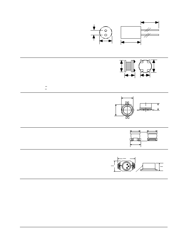
The coil part numbers presented in this data sheet have been qualified as being suitable for the SP4422A product.
Contact Sipex for applications assistance in choosing coil values not listed in this data sheet.
2.5
6.5 Max
9.0 Max
25
Ī
2.0
(All dimensions in mm)
HITACHI METALS Ltd. Japan
Ph: 3-3284-4936
Fax: 3-3287-1945
HITACHI METALS Singapore
Ph: 65-222-3077
Fax: 65-222-5232
Part Numbers:
MD735L902B (9mH + 20% 41
)
MD735L502A (5mH + 20% 19.8
)
HITACHI METALS Hong Kong
Ph: 852-2724-4183
Fax: 852-2311-2093
HITACHI METALS Chicago, IL
Ph: 847-364-7200
Fax: 847-364-7279
Toko Inc. Japan
Ph: 03-3727-1161
Fax: 03-3727-1176
Toko America Inc. USA
Ph: 847-297-0070
Fax: 847-699-7864
Part Numbers:
667MA-472N (4.7mH, 13
)
Toko Inc. Singapore
Ph: 255-4000
Fax: 250-8134
Toko Germany
Ph: 49-7156-96-060
Fax: 49-7156-96-06-26
Toko U.K.
Ph: 1753-854057-9
Fax: 1753-8503-23
Toko Korea
Ph: 0551-50-5500
Fax: 0551-93-1110
Toko France
Ph: 01-4557-4465
Fax: 01-4554-2837
Toko Hong Kong
Ph: 2342-8131
Fax: 2341-9570
(All Dimensions in mm)
4.4 Max
2.75 Max
4.4
5.0
Ī
0.3
5.0
Ī
0.3
5.7
Ī
0.3
4.7
Ī
0.3
(All Dimensions in mm)
muRata USA
Ph: 770-436-1300
Fax: 770-436-3030
muRata Europe
Ph: 49-9116-6870
Fax: 49-1166-8722-5
muRata Taiwan
Ph: 88-6429-1415-1
Fax: 88-6442-5292-9
muRata Singapore
Ph: 65-758-4233
Fax: 65-753-6181
muRata Hong Kong
Ph: 85-2237-6389-8
Fax: 85-2237-5556-55
Part Numbers:
LQN6C472M04 (4.7mH, 35
)
LQN6C103M04 (10mH, 80
)
7.0
Ī
0.5
6.0
Ī
0.3
3.3
Ī
0.3
6.8
Ī
0.3
Coilcraft USA
Ph: 847-639-6400
Fax: 847-639-1469
Coilcraft Europe
Ph: 44-01236-730595
Fax: 44-01236-730627
Part Numbers:
DS1608C-106 (10mH, 32
)
Coilcraft Taiwan
Ph: 886-2-264-3646
Fax: 886-2-270-0294
Coilcraft Singapore
Ph: 65-296-6933
Fax: 465-296-4463 #382
Coilcraft Hong Kong
Ph: 852-770-9428
Fax: 852-770-0729
.175
4,45
.260
6,60 MAX
MAX
.115
2,92 MAX
Magnetically Shielded
(All Dimensions in mm)
(All Dimensions in mm)
CTC Coils LTD Hong Kong
Ph: 85-2695-4889
Fax: 85-2695-1842
Mark Technologies:
North American Stocking
distributor for Sankyo and CTC
Ph: 905-891-0165
Fax: 905-891-8534
Model Numbers: CH5070AS-203K-006 (20
m
H, 65
)
Sipex Number: S51208-M-1021-Sipex

SP4424DS/16
SP4424 Electroluminescent Lamp Driver
© Copyright 2000 Sipex Corporation
10
EL Lamp manufacturers
Metro Mark/Leading Edge
Minnetonka, MN
Phone: (800) 680-5556
Phone: (612) 912-1700
Midori Mark Ltd.
1-5 Komagata 2-Chome
Taita-Ku 111-0043 Japan
Phone: 81-03-3848-2011
Luminescent Systems Inc. (LSI)
Lebanon, NH
Phone: (603) 643-7766
Fax: (603) 643-5947
EL polarizers/transflector
manufacturers
Nitto Denko
San Jose, CA
Phone: (510) 445-5400
Astra Products
Baldwin, NJ
Phone: (516) 223-7500
Fax: (516) 868-2371
NEC Corporation
Tokyo, Japan
Phone: (03) 3798-9572
Fax: (03) 3798-6134
Seiko Precision
Tokyo, Japan
Phone: (03) 5610-7089
Fax: .) 5610-7177
Gunze Electronics
2113 Wells Branch Parkway
Austin, TX 78728
Phone: (512) 752-1299
Fax: (512) 252-1181

SP4424DS/16
SP4424 Electroluminescent Lamp Driver
© Copyright 2000 Sipex Corporation
11
P
W
1
0.228/0.244
0.150/0.157
0.189/0.197
0.014/0.019
0.050 BSC
0.053/0.069
SP4424CN
1
0.013
Ī
0.005
SP4424CU
0.0256
BSC
0.118
Ī
0.002
0.020
2
0.020
0.116
Ī
0.004
0.034
Ī
0.002
0.040
Ī
0.002
0.004
Ī
0.002
0.118
Ī
0.002
0.118
Ī
0.004
0.037
Ref
0.0215
Ī
0.006
3.0į
Ī
3į
R .003
12.0į
Ī
4į
0.006
Ī
0.006
0.006
Ī
0.006
0.008
0į - 6į
0.012
Ī
0.003
0.01
12.0į
Ī
4į
0.16
Ī
0.003
0.0965
Ī
0.003
0.116
Ī
0.004
Pkg.
Minimum qty per reel
Standard qty per reel
Maximum qty per reel
CN
500
2500
3000
CU
500
2500
3000
All package dimensions in inches
95 SP4424CN per tube, no minimum quantity
50 SP4424CU per tube
8-pin NSOIC
8-pin
Ķ
SOIC
NSOIC-8 13" reels: P=8mm, W=12mm
Ķ
SOIC-8 13" reels: P=8mm, W=12mm

SP4424DS/16
SP4424 Electroluminescent Lamp Driver
© Copyright 2000 Sipex Corporation
12
ORDERING INFORMATION
Model
Operating Temperature Range
Package Type
SP4424CN . ............................................ -40įC to +85įC ......................................... 8-Pin NSOIC
SP4424CU . ............................................ -40įC to +85įC ......................................... 8-Pin
Ķ
SOIC
SP4424CX .............................................. -40įC to +85įC ........................................................ Die
SP4424NEB ..................................................... N/A ............................... NSOIC Evaluation Board
SP4424UEB ..................................................... N/A ...............................
Ķ
SOIC Evaluation Board
Please consult the factory for pricing and availability on a Tape-On-Reel option.
Corporation
SIGNAL PROCESSING EXCELLENCE
Sipex Corporation reserves the right to make changes to any products described herein. Sipex does not assume any liability arising out of the
application or use of any product or circuit described hereing; neither does it convey any license under its patent rights nor the rights of others.
Sipex Corporation
Headquarters and
Sales Office
22 Linnell Circle
Billerica, MA 01821
TEL: (978) 667-8700
FAX: (978) 670-9001
e-mail: sales@sipex.com
Sales Office
233 South Hillview Drive
Milpitas, CA 95035
TEL: (408) 934-7500
FAX: (408) 935-7600