Skyworks Solutions, Inc. [978] 241-7000
∑ Fax [978] 241-7906 ∑ Email sales@skyworksinc.com ∑ www.skyworksinc.com
1
Specifications subject to change without notice. 3/99A
Parameter
Condition
Frequency
Min.
Typ.
Max.
Unit
Switching Characteristics
5
Rise, Fall (10/90% or 90/10% RF)
15
ns
On, Off (50% CTL to 90/10% RF)
35
ns
Video Feedthru
30
mV
Input Power for 1 dB Compression
0.50≠2.0 GHz
+26
dBm
Intermodulation Intercept Point (IP3)
For Two-tone Input Power +13 dBm
0.50≠2.0 GHz
+40
dBm
0.05 GHz
+29
dBm
Control Voltages
V
Low
0.0
0.2
V
V
High
4.5
5.0
V
Supply Voltages
+5 V ± 0.20 V @ 3 mA Typ.
-5 V ± 0.20 V @ 16 mA Typ.
6,7
GaAs IC SP4T Non-Reflective Switch
With Integral Driver DC≠2 GHz
Features
Integral Driver ±5 V Supply Voltages
High Isolation (50 dB @ 0.9 GHz)
Low Insertion Loss (0.7 dB @ 0.9 GHz)
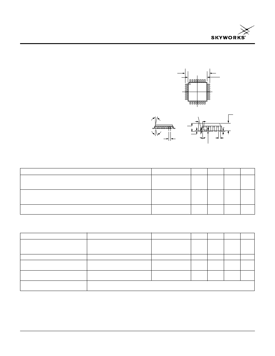
LQFP-32 Plastic Package
Non-Reflective All Ports
LQFP-32
AK115-61
Description
The AK115-61 is a high isolation SP4T FET IC non-
reflective switch with integral driver. The insertion loss is
0.7 dB and isolation is 50 dB at 0.9 GHz. The switch is
ideal for cellular base station switch matrices.
Operating Characteristics at 25∞C (+5, -5 V)
1. All measurements made in a 50
system, unless otherwise specified.
2. DC = 300 kHz.
3. Insertion loss changes by 0.003 dB/∞C.
4. Input/Output.
5. Video feedthru measured with 1 ns risetime pulse and 500 MHz bandwidth.
6. Supply voltage and ground must be connected before control voltage is
applied to avoid irreversible damage to the device.
7. Current increases from 16 mA to 20 mA @ +85∞C.
0.364 (9.25 mm)
0.344 (8.74 mm)
SQ.
0.280 (7.11 mm)
0.272 (6.91 mm)
SQ.
0.031 (0.80 mm)
BSC
R 0.008
(0.20 mm)
0.010 (0.25 mm)
GAGE PLANE
0.030
(0.76 mm)
0.018
(0.46 mm)
0.057
(1.45 mm)
0.053
(1.35 mm)
0.006 (0.15 mm)
0.002 (0.05 mm)
0.018 (0.46 mm)
0.012 (0.30 mm)
0.008
(0.20 mm)
MAX.
0.063
(1.60 mm)
MAX.
0∞ ≠ 7∞
6.0∞ ± 4∞
32
1
12.0∞
TYP.
12.0∞
TYP.
Parameter
1
Frequency
2
Min.
Typ.
Max.
Unit
Insertion Loss
3
DC≠0.5 GHz
0.5
0.7
dB
DC≠1.0 GHz
0.7
0.9
dB
DC≠2.0 GHz
1.1
1.3
dB
Isolation
DC≠0.5 GHz
50
58
dB
DC≠1.0 GHz
45
51
dB
DC≠2.0 GHz
35
39
dB
VSWR
4
DC≠1.0 GHz
1.55:1
1.6:1
DC≠2.0 GHz
1.65:1
1.8:1
Electrical Specifications at 25∞C (+5, -5 V)

2
Skyworks Solutions, Inc. [978] 241-7000
∑ Fax [978] 241-7906 ∑ Email sales@skyworksinc.com ∑ www.skyworksinc.com
Specifications subject to change without notice. 3/99A
GaAs IC SP4T Non-Reflective Switch With Integral Driver DC≠2 GHz
AK115-61
1.2
1.0
0.8
0.6
0.4
0.2
Frequency (GHz)
Insertion Loss vs. Frequency
dB
1
2
DC
+85∞C
-55∞C
2.5
2.2
1.9
1.6
1.3
1.0
Frequency (GHz)
DC
1
2
VSWR vs. Frequency
70
60
50
40
30
20
Frequency (GHz)
Isolation vs. Frequency
dB
DC
1
2
J
1
≠J
3
, J
4
J
1
≠J
2
, J
5
1
24
2
23
3
22
4
21
5
20
6
19
7
18
8
17
32 31 30 29 28 27 26 25
9
50
50
50
50
10 11 12 13 14 15 16
GND
GND
GND
GND
GND
GND
GND
C
2
J
1
C
3
GND
-5 V
+5 V
GND
C
4
C
5
GND
GND
GND
GND
GND
GND
J
2
J
3
GND
GND
GND
GND
GND
GND
J
5
J
4
Typical Performance Data (+5, -5 V)
Characteristic
Value
RF Input Power
0.8 W > 500 MHz
0.2 W @ 50 MHz
Supply Voltage
+7.0 V, -7.0 V
Control Voltage
-0.2 V, +7.0 V
Operating Temperature
0∞C to +70∞C
Storage Temperature
-65∞C to +150∞C
JC
30∞C/W
Absolute Maximum Ratings
Pin Out
Insertion
J
2
J
3
J
4
J
5
Loss
Path J
1
to:
C
2
C
3
C
4
C
5
J
2
0
1
1
1
J
3
1
0
1
1
J
4
1
1
0
1
J
5
1
1
1
0
Truth Table
"0" = 0.0 to 0.2 V, "1" = 4.5 to 5.0 V.