 | –≠–Ľ–Ķ–ļ—ā—Ä–ĺ–Ĺ–Ĺ—č–Ļ –ļ–ĺ–ľ–Ņ–ĺ–Ĺ–Ķ–Ĺ—ā: AL107-84 | –°–ļ–į—á–į—ā—Ć:  PDF PDF  ZIP ZIP |
Skyworks Solutions, Inc. [978] 241-7000
∑
Fax [978] 241-7906
∑
Email sales@skyworksinc.com
∑
www.skyworksinc.com
1
Specifications subject to change without notice. 8/01A
GaAs IC 1800 MHz
High Dynamic Range Amplifier
Features
+33 dBm Output IP3
2.9 dB Noise Figure
Single +5 V Supply
Input and Output Matched to 50
Ideal for Cellular Applications
SOIC-8 with Slug
AL107-84
Description
The AL107-84 is a high dynamic range amplifier for
1800 MHz applications. The amplifier has high input IP3
of 21 dBm, low noise figure of 2.9 dB and operates from
a single positive bias of +5 V. External resistor sets the
amplifier drain current. No external matching elements are
required. As a low noise driver amplifier it is ideally suited
for 1800 MHz wireless base station applications. The
AL107-84 is encapsulated in SOIC-8 package with slug
for improved heat dissipation and reliability.
Parameter
1
Condition
Frequency
Min.
Typ.
Max.
Unit
Small Signal Gain
1700-1900 MHz
10.5
12
dB
Input P
-1 dB
1800 MHz
8
dB
Input IP3
P
IN
= -5 dBm
1800 MHz
18
23
dBm
Noise Figure
1700-1900 MHz
2.9
Reverse Isolation
1700-1900 MHz
22
dB
Input VSWR
1700-1900 MHz
1.5:1
1.8:1
dB
Output VSWR
1700-1900 MHz
1.8:1
2.1:1
Electrical Specifications at 25įC
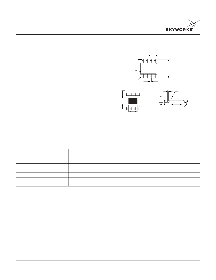
0.049 (1.24 mm)
0.016 (0.41 mm)
0.068
(1.73 mm)
MAX.
0.016 MAX.
(0.41 mm) x
45į CHAMFER
PIN 1
0.106 (2.65 mm)
Ī 0.005 (0.12 mm)
0.066 (1.65 mm)
Ī 0.005 (0.12 mm)
EXPOSED
HEAT SLUG
0.010 (0.25 mm)
0.007 (0.17 mm)
0.158 (4.00 mm)
0.150 (3.80 mm)
8į
MAX.
0.020 (0.51 mm) MAX.
0.244 (6.20 mm)
0.228 (5.80 mm)
0.050 (1.27 mm) BSC
PIN 8
PIN 1
INDICATOR
1. Test condition V
D
= +5 V, I
D
= 65 mA.
GaAs IC 1800 MHz High Dynamic Range Amplifier
AL107-84
2
Skyworks Solutions, Inc. [978] 241-7000
∑
Fax [978] 241-7906
∑
Email sales@skyworksinc.com
∑
www.skyworksinc.com
Specifications subject to change without notice. 8/01A
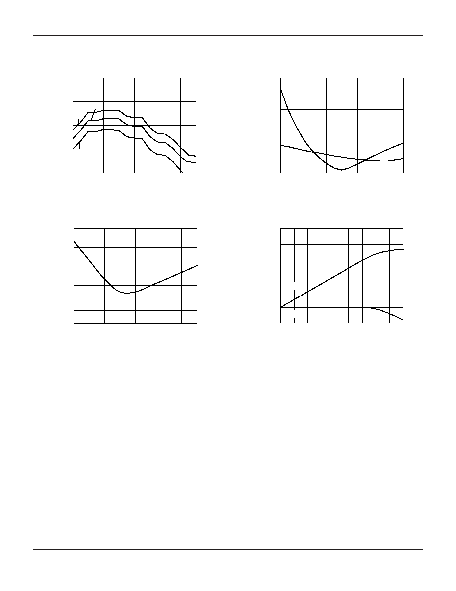
Gain vs. Frequency Over Temperature
Frequency (GHz)
Gain (dB)
10
11
12
13
14
1.4
1.5
1.6
1.7
1.8
1.9
2.0
2.1
2.2
0įC
25įC
70įC
Noise Figure vs. Frequency
Frequency (GHz)
Noise Figure (dB)
2.5
2.7
2.9
3.1
3.3
3.5
3.7
3.9
1.4
1.5
1.6
1.7
1.8
1.9
2.0
2.1
2.2
P
OUT
and Gain vs. P
IN
1750 MHz
P
IN
(dBm)
Gain (dB) and P
OUT
(dBm)
10
12
14
16
18
20
22
0
1
2
3
4
5
6
7
8
9
GAIN
P
OUT
Input and Output vs. Frequency
Frequency (GHz)
VSWR
1.0
1.5
2.0
2.5
3.0
3.5
4.0
1.4
1.5
1.6
1.7
1.8
1.9
2.0
2.1
2.2
Output
Input
Typical Performance Data at 25įC
GaAs IC 1800 MHz High Dynamic Range Amplifier
AL107-84
Skyworks Solutions, Inc. [978] 241-7000
∑
Fax [978] 241-7906
∑
Email sales@skyworksinc.com
∑
www.skyworksinc.com
3
Specifications subject to change without notice. 8/01A
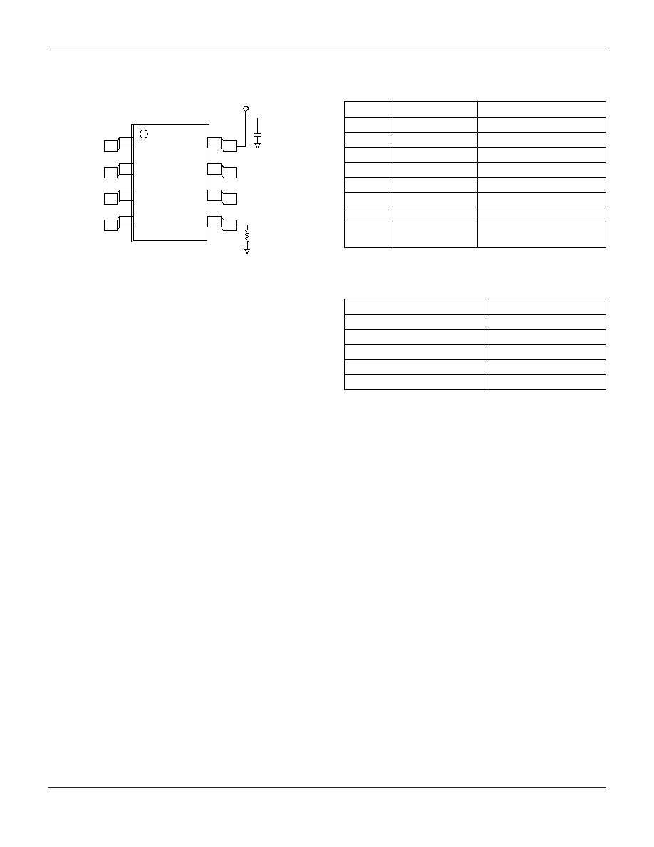
12
3
4
87
6
5
C
BL
GND
RF Out
GND
RF In
GND
GND
V
D
Pin Out
Terminal
Symbol
Function
1
GND
Ground
2
GND
Ground
3
RF In
RF Input
4
GND
Ground
5
R
Current Set External Resistor
6
RF Out
RF Output
7
GND
Ground
8
V
D
+5 V Supply Through
Bypass Cap
Pin Configuration
Characteristic
Value
Drain Voltage (V
D
)
7 V
Current (I
D
)
100 mA
Input Power (P
IN
)
20 dBm
Operating Temperature (T
OP
)
-30 to +100įC
Storage Temperature (T
ST
)
-65 to +120įC
Absolute Maximum Ratings
Power Supply and Current Settings
V
D
of +5 V is fed to pin 8. A 100 pF bypass capacitor
should be placed as close as possible to the lead. The
current can be set 50-80 mA by changing value of the
external resistor connected to pin 6. Typical values for the
resistor (R) are 12≠24
.