 | –≠–ª–µ–∫—Ç—Ä–æ–Ω–Ω—ã–π –∫–æ–º–ø–æ–Ω–µ–Ω—Ç: AM107-602 | –°–∫–∞—á–∞—Ç—å:  PDF PDF  ZIP ZIP |

Skyworks Solutions, Inc. [781] 376-3000
∑
Fax [781] 376-3100
∑
Email sales@skyworksinc.com
∑
www.skyworksinc.com
1
Specifications subject to change without notice. 8/03A
Dual-Band GaAs IC
Antenna Switch Module
AM107
Outline Drawing
PIN 1 INDICATOR
PIN
1
PIN 10
5.40
4.00
1.70
2X 2.30
2X 1.80
2X 1.40
2X 0.60
2X 0.25
2X 0.40
8X 2.00
8X 1.50
3X 1.10
2X 1.00
2X 0.39
2X 0.35
8X 0.50
8X 0.50
4X 1.00
2X 1.20
TOP VIEW
SIDE VIEW
BOTTOM VIEW
LOT NO.
AM107
YYWW CC
Description
The AM107-602 is a GSM850/PCS or EGSM/DCS
dual-band antenna switch module with integrated SP2T
GaAs PHEMT switches, decoder for 2 line control, T
X
low
pass filters and diplexer. It is housed in a 11 pin
5.4 x 4.0 x 1.7 mm LTCC multilayer ceramic package. The
module has internal ESD protection to 2000 V. For
protection to 8 kV and higher, contact factory for
application note.
Features
Integrated Diplexer, T
X
LPFs, PHEMT
GaAs Switches and Decoder
Operates in GSM850/PCS or EGSM/DCS
Bands
Low Current Drain, < 10
µ
A Typ.
Low T
X
Insertion Loss
(0.9 dB @ GSM, 1.3 dB @ DCS/PCS)
ESD Robust (> 8 kV Contact, >15 kV Air)
Combines GaAs PHEMT, CMOS and
LTCC Process Technologies
Applications
Dual-Band Antenna Switch for GSM
Handsets
Dimensions in mm.
Tolerance ± 0.2 mm unless otherwise specified.

Dual-Band GaAs IC Antenna Switch Module
AM107
2
Skyworks Solutions, Inc. [781] 376-3000
∑
Fax [781] 376-3100
∑
Email sales@skyworksinc.com
∑
www.skyworksinc.com
Specifications subject to change without notice. 8/03A
Mode
Parameter
Min.
Typ.
Max.
Unit
GSM850/EGSM_T
X
to Ant
Passband - GSM850_T
X
824
836.5
849 MHz
Passband - EGSM_T
X
880
897.5
915
MHz
Insertion Loss - GSM850_T
X
0.7
0.9
dB
Insertion Loss - GSM850_T
X
(-30 to +85∞C)
0.9
1.1
dB
Insertion Loss - EGSM_T
X
0.9
1.1
dB
Insertion Loss - EGSM_T
X
(-30 to +85∞C)
1.1
1.3
dB
Attenuation 1648≠1830 MHz (2*F
O
)
25
30
dB
Attenuation 2472≠2745 MHz (3*F
O
)
30
35
dB
Return Loss GSM850_T
X
(I/O) 14
18
dB
Return Loss EGSM_T
X
(I/O)
14
18
dB
Isolation DCS/PCS_T
X
- EGSM_R
X
25
30
dB
Isolation DCS/PCS_T
X
- DCS_R
X
23
28
dB
Isolation DCS/PCS_T
X
- PCS_R
X
25
30
dB
Harmonic Generation 1648≠1830 MHz (2*F
O
)
70
80
dBc
Harmonic Generation 2472≠2745 MHz (3*F
O
)
70
80
dBc
Input Power
34.5
35
dBm
Current Consumption (-30 to +85∞C) V
CC
= 3 V
10
100
µ
A
DCS/PCS_T
X
to Ant
Passband - DCS_T
X
1710
1747.5
1785
MHz
Passband - PCS_T
X
1850
1880
1910
MHz
Insertion Loss - DCS_T
X
1.4
1.6
dB
Insertion Loss - DCS_T
X
(-30 to +85∞C)
1.6
1.8
dB
Insertion Loss - PCS_T
X
1.3
1.5
dB
Insertion Loss - PCS_T
X
(-30 to +85∞C)
1.5
1.7
dB
Attenuation 3420≠3820 MHz (2*F
O
)
25
35
dB
Attenuation 5130≠5730 MHz (3*F
O
)
30
40
dB
Return Loss DCS_T
X
(I/O) 12
15
dB
Return Loss PCS_T
X
(I/O)
14
18
dB
Isolation DCS/PCS_T
X
- EGSM_R
X
25
30
dB
Isolation DCS/PCS_T
X
- DCS_R
X
23
28
dB
Isolation DCS/PCS_T
X
- PCS_R
X
25
30
dB
Harmonic Generation 3420≠3820 MHz (2*F
O
)
67
70
dBc
Harmonic Generation 5130≠5730 MHz (3*F
O
)
67
75
dBc
Input Power
32.5
33
dBm
Current Consumption (-30 to +85∞C) V
CC
= 3 V
10
100
µ
A
T
X
Specification

Dual-Band GaAs IC Antenna Switch Module
AM107
Skyworks Solutions, Inc. [781] 376-3000
∑
Fax [781] 376-3100
∑
Email sales@skyworksinc.com
∑
www.skyworksinc.com
3
Specifications subject to change without notice. 8/03A
Mode
Parameter
Min.
Typ.
Max.
Unit
Ant to GSM850_R
X
Passband
869
881.5
894
MHz
Insertion Loss
0.7
0.9
dB
Insertion Loss (-30 to +85∞C) V
CC
= 3 V
0.9
1.1
dB
Return Loss (I/O)
14
18
dB
Isolation GSM850_T
X
- Ant
17
21
dB
Input Power
10
dBm
Current Consumption
5
15
µ
A
Ant to EGSM_R
X
Passband
925
942.5
960
MHz
Insertion Loss
0.8
1.0
dB
Insertion Loss (-30 to +85∞C) V
CC
= 3 V
1.0
1.2
dB
Return Loss (I/O)
14
18
dB
Isolation EGSM_T
X
- Ant
17
21
dB
Input Power
10
dBm
Current Consumption
5
15
µ
A
Ant to DCS_R
X
Passband 1805
1842.5
1880
MHz
Insertion Loss
1.1
1.3
dB
Insertion Loss (-30 to +85∞C) V
CC
= 3 V
1.3
1.5
dB
Return Loss (I/O)
14
17
dB
Isolation DCS_T
X
- Ant
15
18
dB
Isolation PCS_R
X
- Ant
23
26
dB
Input Power
10
dBm
Current Consumption
5
15
µ
A
Ant to PCS_R
X
Passband
1930
1960
1990
MHz
Insertion Loss
1.2
1.4
dB
Insertion Loss (-30 to +85∞C) V
CC
= 3 V
1.4
1.6
dB
Return Loss (I/O)
12
15
dB
Isolation PCS_T
X
- Ant
14
17
dB
Isolation DCS_R
X
- Ant
23
26
dB
Input Power
10
dBm
Current Consumption
5
15
µ
A
Control Voltage
V
C1
, V
C2
, V
C3
High "1"
V
CC
-0.6
V
CC
V
V
C1
, V
C2
, V
C3
Low "0"
0
0.5
V
Supply Voltage
V
CC
2.6
3.0
5.0
V
R
X
Specification
Characteristic
Value
Operating Temp Range (T
OP
)
-30 to +85∞C
Storage Temp Range (T
STG
)
-40 to +85∞C
Input Power, EGSM_T
X
(P
IN
EGSM_T
X
)
36 dBm
Input Power, DCS_T
X
(P
IN
DCS_T
X
)
34 dBm
Control Voltage Logic 0 (V
C1
, V
C2
, V
C3
)
-0.1 to +0.8 V
Control Voltage Logic 1 (V
C1
, V
C2
, V
C3
)
V
CC
+ 0.1 V
Supply Voltage (V
CC
)
6 V
Nominal I/O Impedances (T
X
, R
X
, Ant)
50
Absolute Maximum Ratings
Switch Mode
1
V
C1
V
C2
EGSM_T
X
1
0
EGSM_R
X
0
0
DCS_T
X
0
1
DCS_R
X
0
0
Truth Table
1. V
CC
voltage must be applied 10 ns (min.) before application of control
voltages (V
C1
, V
C2
).
Dual-Band GaAs IC Antenna Switch Module
AM107
4
Skyworks Solutions, Inc. [781] 376-3000
∑
Fax [781] 376-3100
∑
Email sales@skyworksinc.com
∑
www.skyworksinc.com
Specifications subject to change without notice. 8/03A
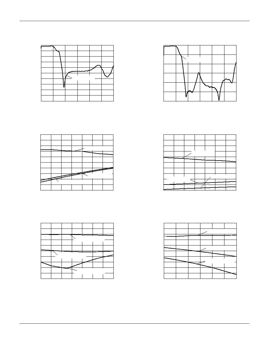
1
2
3
4
5
6
Frequency (GHz)
Ant - GSM850/EGSM R
X
S
21
Insertion Loss (dB)
0
-50
-45
-40
-35
-30
-25
-20
-15
-10
-5
0
GSM_R
X
S
21
1
2
3
4
5
6
Frequency (GHz)
GSM850/EGSM T
X
S
21
- Ant
Insertion Loss (dB)
0
-60
-50
-40
-30
-20
-10
0
GSM_T
X
S
21
Frequency (GHz)
Ant - EGSM R
X
In Band
Insertion Loss (dB)
-1.5
-1.4
-1.3
-1.2
-1.1
-1.0
-0.9
-0.8
-0.7
-0.6
-0.5
0.925
0.935
0.945
0.955
-25.0
-22.5
-20.0
-17.5
-15.0
-12.5
-10.0
-7.5
-5.0
EGSM_R
X
S
21
EGSM_R
X
S
11
EGSM_R
X
S
22
0.930
0.940
0.950
0.960
Frequency (GHz)
EGSM T
X
In Band - Ant
Insertion Loss (dB)
-1.5
-1.4
-1.3
-1.2
-1.1
-1.0
-0.9
-0.8
-0.7
-0.6
-0.5
0.880
0.890
0.900
0.910
-20
-18
-16
-14
-12
-10
-8
-6
-4
-2
0
EGSM_T
X
S
21
EGSM_T
X
S
11
EGSM_T
X
S
22
0.885
0.895
0.905
0.915
Frequency (GHz)
Ant - GSM850 R
X
In Band
Insertion Loss (dB)
-1.5
-1.4
-1.3
-1.2
-1.1
-1.0
-0.9
-0.8
-0.7
-0.6
-0.5
0.865
0.875
0.885
0.895
-50
-45
-40
-35
-30
-25
-20
-15
-10
-5
0
GSM850_R
X
S
21
GSM850_R
X
S
11
GSM850_R
X
S
22
0.870
0.880
0.890
0.900
Frequency (GHz)
GSM850 T
X
In Band - Ant
Insertion Loss (dB)
-1.5
-1.4
-1.3
-1.2
-1.1
-1.0
-0.9
-0.8
-0.7
-0.6
-0.5
0.820
0.825 0.830
0.835
0.840
0.845 0.850
-30
-28
-26
-24
-22
-20
-18
-16
-14
-12
-10
GSM850_T
X
S
21
GSM850_T
X
S
11
GSM850_ T
X
S
22
Typical Performance Data (0, +3 V)

Dual-Band GaAs IC Antenna Switch Module
AM107
Skyworks Solutions, Inc. [781] 376-3000
∑
Fax [781] 376-3100
∑
Email sales@skyworksinc.com
∑
www.skyworksinc.com
5
Specifications subject to change without notice. 8/03A
1
2
3
4
5
6
Frequency (GHz)
DCS/PCS T
X
S
21
- Ant
Insertion Loss (dB)
0
-50
-45
-40
-35
-30
-25
-20
-15
-10
-5
0
DCS_T
X
S
21
1
2
3
4
5
6
Frequency (GHz)
Ant - DCS/PCS R
X
S
21
Insertion Loss (dB)
0
-50
-45
-40
-35
-30
-25
-20
-15
-10
-5
0
DCS_R
X
S
21
Frequency (GHz)
DCS T
X
In Band - Ant
Insertion Loss (dB)
-2.0
-1.9
-1.8
-1.7
-1.6
-1.5
-1.4
-1.3
-1.2
-1.1
-1.0
1.71 1.72 1.73 1.74 1.75 1.76 1.77 1.78 1.79
-25.0
-22.5
-20.0
-17.5
-15.0
-12.5
-10.0
-7.5
-5.0
DCS_T
X
S
21
DCS_T
X
S
11
DCS_T
X
S
22
Frequency (GHz)
Ant - DCS R
X
In Band
Insertion Loss (dB)
-2.0
-1.9
-1.8
-1.7
-1.6
-1.5
-1.4
-1.3
-1.2
-1.1
-1.0
1.80 1.81 1.82 1.83 1.84 1.85 1.86 1.87 1.88
-20
-18
-16
-14
-12
-10
-8
-6
-4
-2
0
DCS_R
X
S
21
DCS_R
X
S
11
DCS_R
X
S
22
Frequency (GHz)
PCS T
X
In Band - Ant
Insertion Loss (dB)
-2.0
-1.9
-1.8
-1.7
-1.6
-1.5
-1.4
-1.3
-1.2
-1.1
-1.0
1.85
1.86
1.87
1.88
1.89
1.90
1.91
-25.0
-22.5
-20.0
-17.5
-15.0
-12.5
-10.0
-7.5
-5.0
PCS_T
X
S
21
PCS_T
X
S
11
PCS_T
X
S
22
Frequency (GHz)
Ant - PCS R
X
In Band
Insertion Loss (dB)
-1.5
-1.4
-1.3
-1.2
-1.1
-1.0
-0.9
-0.8
-0.7
-0.6
-0.5
1.93
1.94
1.95
1.96
1.97
1.98
1.99
-20
-18
-16
-14
-12
-10
-8
-6
-4
-2
0
PCS_R
X
S
21
PCS_R
X
S
11
PCS_R
X
S
22

Dual-Band GaAs IC Antenna Switch Module
AM107
6
Skyworks Solutions, Inc. [781] 376-3000
∑
Fax [781] 376-3100
∑
Email sales@skyworksinc.com
∑
www.skyworksinc.com
Specifications subject to change without notice. 8/03A
Pin Out Description
Pin Out (Top View)
Pin Number
Description
Remarks
1
DCS_T
X
50
Terminating Impedance
2
V
CC
Power Supply
3
V
C1
Control Input
4
V
C2
Control Input
5
GSM_T
X
50
Terminating Impedance
6
GSM_R
X
50
Terminating Impedance
7, 9, 11
GND
Ground
8
ANT
50
Terminating Impedance
10
DCS_R
X
50
Terminating Impedance
DCS_T
X
V
C2
V
CC
V
C1
GSM_T
X
DCS_R
X
GND
ANT
GND
GSM_R
X
1
2
3
4
5
6
7
8
9
10
11
GND
Block Diagram
ESGM_R
X
V
CC
V
C1
V
C2
R
X
T
X
R
X
T
X
DCS_R
X
ESGM_T
X
DCS_T
X
SP2T
GaAs Switch
SP2T
GaAs Switch
LPF
LPF
Decoder
Antenna
Diplexer
Suggested Land Pattern
0.165 (4.20 mm)
0.142 (3.60 mm)
0.125 (3.17 mm)
0.106
(2.70 mm)
0.059 (1.50 mm)
0.041 (1.03 mm)
0.024 (0.60 mm)
0.039
(1.00 mm)
0.022
(0.55 mm)
TYP.
0.063
(1.60 mm)
0.013 (0.33 mm) TYP.
PLATED THRU VIAS
FOR GROUNDING
0.213
(5.40 mm)
0.032
(0.81 mm)
0.013
(0.32 mm)
0.017 (0.43 mm)
Evaluation PCB
J
1
J
2
J
3
J
4
J
5
AM107-602
C
1
C
2
C
3
C
4
C
5
C
6
EGSM R
X
DCS R
X
EGSM T
X
CTL2
CTL1
SK39423
REV 2
DUAL BAND
ANTENNA SWITCH
GSM/DCS
(5.4 x 4.0 mm)
1
ANT
V
CC
DCS T
X
Item
Description
J
1
≠J
5
PC Mount SMA Connector
C
1
≠C
5
47 pF Surface Mount Capacitor
C
6
0.01 µF Surface Mount Capacitor
PCB
1
SK39423 Evaluation PCB
1. Circuit Board Material: FR4

Dual-Band GaAs IC Antenna Switch Module
AM107
Skyworks Solutions, Inc. [781] 376-3000
∑
Fax [781] 376-3100
∑
Email sales@skyworksinc.com
∑
www.skyworksinc.com
7
Specifications subject to change without notice. 8/03A
Tape Orientation
User Direction of Feed
Pin 1
12.0 mm
Standard Reel Size
7"
13"
Standard Reel Quantity*
1,000
3,000