 | –≠–ª–µ–∫—Ç—Ä–æ–Ω–Ω—ã–π –∫–æ–º–ø–æ–Ω–µ–Ω—Ç: DD02-92LF | –°–∫–∞—á–∞—Ç—å:  PDF PDF  ZIP ZIP |
Skyworks Solutions, Inc. ∑ Phone [781] 376-3000 ∑ Fax [781] 376-3100 ∑ sales@skyworksinc.com ∑ www.skyworksinc.com
200036 Rev. A ∑ Skyworks Proprietary Information ∑ Products and Product Information are Subject to Change Without Notice. ∑ September 27, 2004
1
DD02-92, DD02-92LF: Directional Detector
DATA SHEET
Features
Frequency coverage: 650 MHz to 3.0 GHz
Typical insertion loss < 0.2 dB to 2.3 GHz
Typical directivity > 23 dB
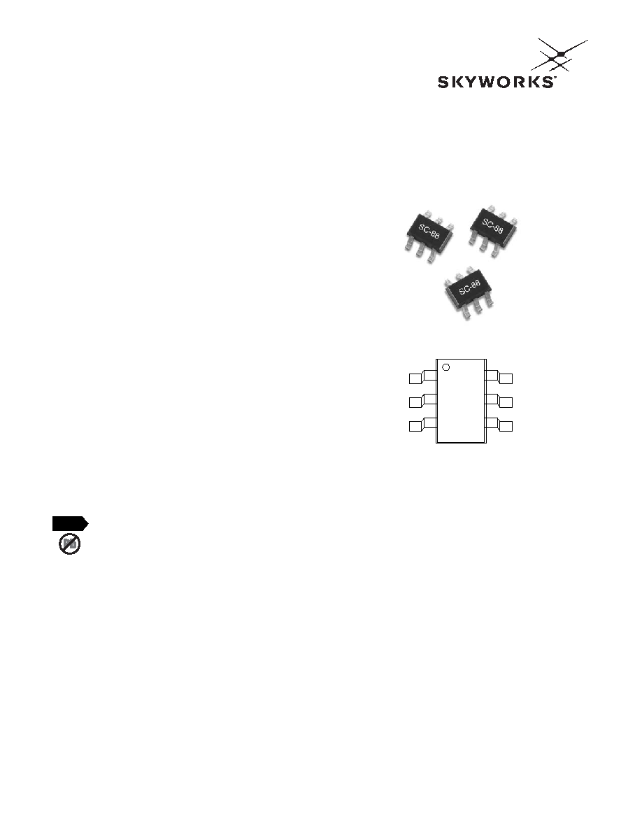
Small outline SC-88 (6 Lead SC-70)
Built-in temperature compensating diode
Low cost for high-volume handset applications
Available lead (Pb)-free MSL-2 @ 250 ∞C per JEDEC J-STD-020
Description
The DD02-92 directional detector is an alternative to the DD01-92
with improved insertion loss and directivity with slightly lower
sensitivity. It is designed for handset power monitor applications
from 800 MHz to 3 GHz. It is packaged in the small footprint,
SC-88 (6 lead SC-70) package. The DD02-92 incorporates a
directional coupler and two GaAs Schottky diodes on a monolithic
GaAs chip. By applying forward DC bias to both Schottky diodes,
the DD02-92 may be conveniently temperature compensated. The
DD02-92 is characterized from 500 MHz to 3 GHz and generates
a detected signal at 1.8 GHz of approximately 190 mV at 10 mW
input power. Each Schottky diode is forward biased to approxi-
mately 5 µA.
12
3
65
4
RF Out
DC Bias/AC GND
Temp Comp Out
DD2
RF In
DC Bias/AC GND
Detected Out
Pin Out
Skyworks offers lead (Pb)-free "environmentally
friendly" packaging that is RoHS compliant
(European Parliament for the Restriction of
Hazardous Substances).
NEW
Skyworks Solutions, Inc. ∑ Phone [781] 376-3000 ∑ Fax [781] 376-3100 ∑ sales@skyworksinc.com ∑ www.skyworksinc.com
September 27, 2004 ∑ Skyworks Proprietary Information ∑ Products and Product Information are Subject to Change Without Notice. ∑ 200036 Rev. A
DATA SHEET ∑ DD02-92, DD02-92LF
2
Parameter
Frequency
Min.
Typ.
Max.
Unit
Detected output voltage @ 10 dBm
0.8≠1.2 GHz
60
80
105
mV
1.8≠2.0 GHz
130
160
190
mV
Insertion loss
0.8≠1.2 GHz
0.10
0.20
dB
1.8≠2.0 GHz
0.20
0.30
dB
Input return loss
0.8≠1.2 GHz
30
22
dB
1.8≠2.0 GHz
25
20
dB
Output return loss
0.8≠1.2 GHz
30
22
dB
1.8≠2.0 GHz
25
20
dB
Directivity
0.8≠1.2 GHz
17
20
dB
1.8≠2.0 GHz
16
13
dB
Schottky noise voltage (1 MHz bandwidth)
RF power off
200
µV
Schottky diode DC voltage
RF power off
510
mV
DC offset voltage
RF power off
-5
0
+5
mV
Video resistance
RF power off
7500
Electrical Specifications at 25 ∞C
Conditions: 10 dBm input power, 1 V applied to Pin 2 and 5 (See test circuit).
All data was taken with R
LOAD
= 100 k
.
Detected output voltage is the difference between V
REF
and V
DET
. A digital voltmeter was used
as a differential amplifier.

DATA SHEET ∑ DD02-92, DD02-92LF
Skyworks Solutions, Inc. ∑ Phone [781] 376-3000 ∑ Fax [781] 376-3100 ∑ sales@skyworksinc.com ∑ www.skyworksinc.com
200036 Rev. A ∑ Skyworks Proprietary Information ∑ Products and Product Information are Subject to Change Without Notice. ∑ September 27, 2004
3
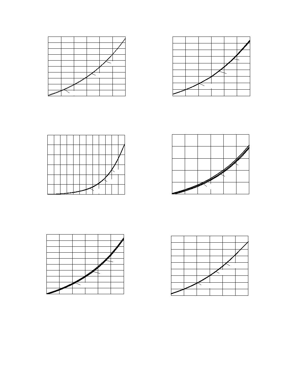
Typical Performance Data
Insertion Loss vs. Frequency
Frequency (GHz)
Loss (dB)
-1.50
-1.25
-1.00
-0.75
-0.50
-0.25
0
0.5
1.0
1.5
2.0
2.5
3.0
Return Loss vs. Frequency
Frequency (GHz)
Return Loss (dB)
-50
-45
-40
-35
-30
-25
-20
-15
-10
-5
0
0.5
1.0
1.5
2.0
2.5
3.0
Input Return Loss
Output Return Loss
Differential Detected Voltage
vs. Frequency & Power
Frequency (GHz)
Detected Voltage (V)
0
0.5
1.0
1.5
2.0
2.5
3.0
3.5
4.0
4.5
5.0
0.5 0.7 0.9 1.1 1.3 1.5 1.7 1.9 2.1 2.3 2.5
+25 dBm
+30 dBm
+35 dBm
Differential Detected Voltage
vs. Frequency and Power
Frequency (GHz)
Detected Voltage (V)
0
0.2
0.4
0.6
0.8
1.0
1.2
0.5 0.7 0.9 1.1 1.3 1.5 1.7 1.9 2.1 2.3 2.5
5 dBm
10 dBm
15 dBm
20 dBm
Differential Detected Voltage vs.
Power and Temperature @ 900 MHz
Power (dBm)
Detected Voltage (V)
0
2
4
6
8
10
12
0
0.01
0.02
0.03
0.04
0.05
0.06
0.07
0.08
0.09
0.10
25 ∞C
85 ∞C
-40 ∞C
Differential Detected Voltage vs.
Power and Temperature @ 900 MHz
Power (dBm)
Detected Voltage (V)
0
0.5
1.0
1.5
2.0
2.5
3.0
0
3
6
9
12 15 18 21 24 27 30 33 36
25 ∞C
85 ∞C
-40 ∞C
Skyworks Solutions, Inc. ∑ Phone [781] 376-3000 ∑ Fax [781] 376-3100 ∑ sales@skyworksinc.com ∑ www.skyworksinc.com
September 27, 2004 ∑ Skyworks Proprietary Information ∑ Products and Product Information are Subject to Change Without Notice. ∑ 200036 Rev. A
DATA SHEET ∑ DD02-92, DD02-92LF
4
Differential Detected Voltage vs.
Power and Temperature @ 900 MHz
Power (dBm)
Detected Voltage (V)
0.09
0.14
0.19
0.24
0.29
0.34
0.39
0.44
0.49
0.54
0.59
12
14
16
18
20
22
24
25 ∞C
85 ∞C
-40 ∞C
Differential Detected Voltage vs.
Power and Temperature @ 900 MHz
Power (dBm)
Detected Voltage (V)
0.50
0.75
1.00
1.25
1.50
1.75
2.00
2.25
2.50
2.75
24
26
28
30
32
34
36
25 ∞C
85 ∞C
-40 ∞C
Differential Detected Voltage vs.
Power and Temperature @ 1900 MHz
Power (dBm)
Detected Voltage (V)
0
2
4
6
8
10
12
0
0.05
0.10
0.15
0.20
0.25
25 ∞C
85 ∞C
-40 ∞C
Differential Detected Voltage vs.
Power and Temperature @ 1900 MHz
Power (dBm)
Detected Voltage (V)
0
1.0
2.0
3.0
4.0
5.0
6.0
0
3
6
9
12 15 18 21 24 27 30 33 36
25 ∞C
85 ∞C
-40 ∞C
Differential Detected Voltage vs.
Power and Temperature @ 1900 MHz
Power (dBm)
Detected Voltage (V)
1.0
1.5
2.0
2.5
3.0
3.5
4.0
4.5
5.0
5.5
24
26
28
30
32
34
36
25 ∞C
85 ∞C
-40 ∞C
Differential Detected Voltage vs.
Power and Temperature @ 1900 MHz
Power (dBm)
Detected Voltage (V)
0.2
0.3
0.4
0.5
0.6
0.7
0.8
0.9
1.0
1.1
1.2
12
14
16
18
20
22
24
25 ∞C
85 ∞C
-40 ∞C

DATA SHEET ∑ DD02-92, DD02-92LF
Skyworks Solutions, Inc. ∑ Phone [781] 376-3000 ∑ Fax [781] 376-3100 ∑ sales@skyworksinc.com ∑ www.skyworksinc.com
200036 Rev. A ∑ Skyworks Proprietary Information ∑ Products and Product Information are Subject to Change Without Notice. ∑ September 27, 2004
5
220 pF
RF Out
22 nH
Bias In
V
REF
100 pF
1.8 k
1.8 k
100 pF
100 k
100 k
V
DET
RF In
SK39374
Rev 2
DD2
DD0*-92
Evaluation Board Layout
0.079 (2.00 mm)
± 0.008 (0.20 mm)
0.049 (1.25 mm)
± 0.004 (0.10 mm)
0.008 (0.20 mm)
± 0.004 (0.10 mm)
0.087 (2.20 mm)
± 0.008 (0.20 mm)
0.035 (0.90 mm)
± 0.004 (0.10 mm)
0.002 (0.005 mm)
± 0.002 (0.005 mm)
0.037 (0.95 mm)
± 0.006 (0.15 mm)
0.010 (0.25 mm)
± 0.006 (0.15 mm)
0.0055
(0.14 mm)
± 0.0015
(0.04 mm)
0.0256 (0.65 mm)
BSC
0.009 (0.23 mm)
Ref.
Pin 1 Indicator
SC-88 (6 Lead SC-70)
RF In
RF Out
6
5
4
3
2
1
100 pF
100 k
1.0 V
1.8 k
1.8 k
22 nH
1 V
Bias
100 pF
100 k
150 pF
+
≠
Differential
Amplifier
Detect Out
V
DET
V
REF
Test Circuit
Characteristic
Value
Incident power (CW)
4 W @ < 1 GHz
@ SWR = 2.0 max.
2 W @ 1≠2.5 GHz
DC bias current
10 mA
Operating temperature
-40 to +85 ∞C
Storage temperature
-65 to +150 ∞C
Absolute Maximum Ratings
Performance is guaranteed only under the conditions listed in the specifications table and is
not guaranteed under the full range(s) described by the Absolute Maximum specifications.
Exceeding any of the absolute maximum/minimum specifications may result in permanent
damage to the device and will void the warranty.
CAUTION: Although this device is designed to be as robust as
possible, Electrostatic Discharge (ESD) can damage
this device. This device must be protected at all times
from ESD. Static charges may easily produce poten-
tials of several kilovolts on the human body or
equipment, which can discharge without detection.
Industry-standard ESD precautions must be employed
at all times.