 | –≠–ª–µ–∫—Ç—Ä–æ–Ω–Ω—ã–π –∫–æ–º–ø–æ–Ω–µ–Ω—Ç: GXB2000 | –°–∫–∞—á–∞—Ç—å:  PDF PDF  ZIP ZIP |

16-Channel GPS Receiver Module
Description
The GXB2000 is a 16-channel GPS receiver module. The GXB2000 is a small and light device, and it
includes all the functions required for GPS except for the antenna.
The GXB2000 can be support the various kinds of the portable applications as well as the car navigation system.
Features
∑ 16-channel GPS receiver capable of simultaneously receiving 16 satellites
∑ All-in-view measurement
∑ 2-satellite measurement
∑ D-GPS (Differential GPS)
RTCM
SC104 version 2.1
DARC
BTA R-003 standard
∑ Low current consumption (270mW, Typ)
∑ Small and light package type
∑ The countermeasure of EMI (electromagnetic wave impediment)
Recommended Operating Conditions
∑ Supply voltage (3V spec.)
V
DD
3.0 to 3.6
V
(5V spec.)
V
CC
4.5 to 5.5
V
∑ Operating temperature
Topr
≠40 to +85
∞C
GPS (Global Positioning System) is the position measurrment system that the U.S. control and operate. It have some posibility of
the position measurement deterioration that depends on the working GPS.
It dose not gurantee the standard,etc in this material including the case above.
≠ 1 ≠
E99658-PS
Sony reserves the right to change products and specifications without prior notice. This information does not convey any license by
any implication or otherwise under any patents or other right. Application circuits shown, if any, are typical examples illustrating the
operation of the devices. Sony cannot assume responsibility for any problems arising out of the use of these circuits.
GXB2000

≠ 2 ≠
GXB2000
Specification
Specification of reception unit
Reception method
Parallel 16 channels
RF input
Reception frequency
1575.42MHz L1 band, C/A code
Characteristics impedance
50
Reception sensitivity
≠130dBm or less
(Sony's recommended anntena input level)
Positioning system
WGS-84
Positioning accuracy
Position
100m 2DRMS
(SA ON, PDOP = 2.5, HDOP = 1.5)
Velocity
0.9m/s
(SA ON, PDOP = 2.5, HDOP = 1.5)
Positioning condition
A) DOP limit
3D: PDOP
12
2D: HDOP
6
B) Elevation mask: 5∞ or more
Follow-up performance
Velocity
500km/h or less
Acceleration
2G or less
Measured data update time
Every 1s
D-GPS function
DARC BTA R-003 standard
RTCM SC104 version 2.1
(6 of 8 format)
Using type 1 data for correct caluculation
Measurement method
All-in-view measurement
2-satellite measurement

≠ 3 ≠
GXB2000
TTFF (No signal break)
1
Hot Start (time, position, with ephemeris and almanac)
7 to 20s
Warm Start (time, position, without ephemeris, with almanac)
33 to 50s
Cold Start (time, position, without ephemeris and almanac)
35 to 60s
Reacquisition Time (interrupt recovery time)
The case of the interrupt less than 5 minutes 2 to 6s
The case of the interrupt more than 5 minutes 6 to 10s
1
Condition: The case of meeting positioning condition and receiving 8 satellites continuously and normally.
Conditons of Cold Start
Abnormal RAM data and abnormal RTC data for
the command input
RF input connector
JST: CN connector
I/O connector (Power supply, data mode)
JST: SM10B-SRSS
Communication Specification
Communication method
Start-stop synchronization
Transfer rate input/output
9600bps
Electric level
TTL level
I/O code
ASCII code
Communication format
Sony/NMEA0183 switching possible
Electrical Specification
Supply voltage (3V spec.)
3.1 to 3.6V Ripple 50mVp-p or less
(5V spec.)
4.5 to 5.5V Ripple 50mVp-p or less
Current consumption
82mA typ. (Vcc = 3.3V, 25∞C)
Backup supply voltage
1.8 to 3.0V
current
30µA typ. (+B = 3.0V, 25∞C)
70µA max. (+B = 3.0V, 85∞C)
Pre-amplifier power supply
2.7 to 3.6V, 10 to 30mA
Operating temperature
≠40 to +85∞C
≠ 4 ≠
GXB2000
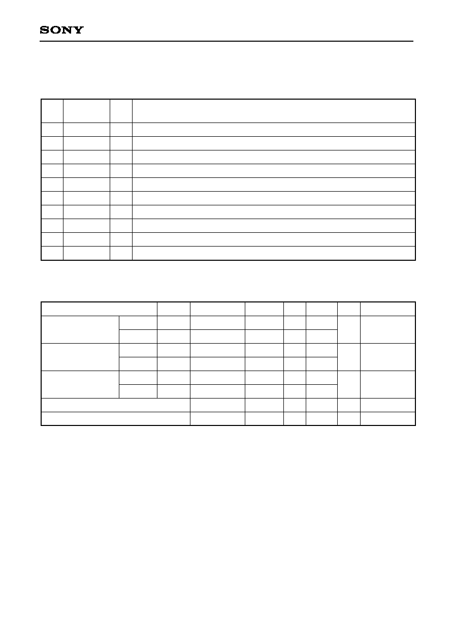
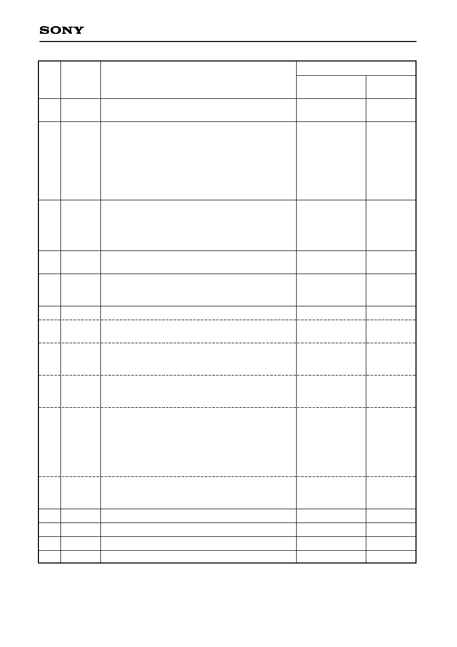
I/O Connector Pin
Pin Configuration
Pin
No.
Symbol
I/O
Description
1
2
3
4
5
6
7
8
9
10
V
CC
RESET
TXD0
RXD0
RXD1
MODE
NC
+BU
NC
GND
--
I
O
I
I
I
--
--
--
--
Main power supply.
Reset input for initializing the reception unit.
Measured data output.
Command input.
D-GPS data input.
Communication format switching pin. (L = Sony, H = NMEA0183)
No connection.
Power supply for backup.
Fixed H level.
GND
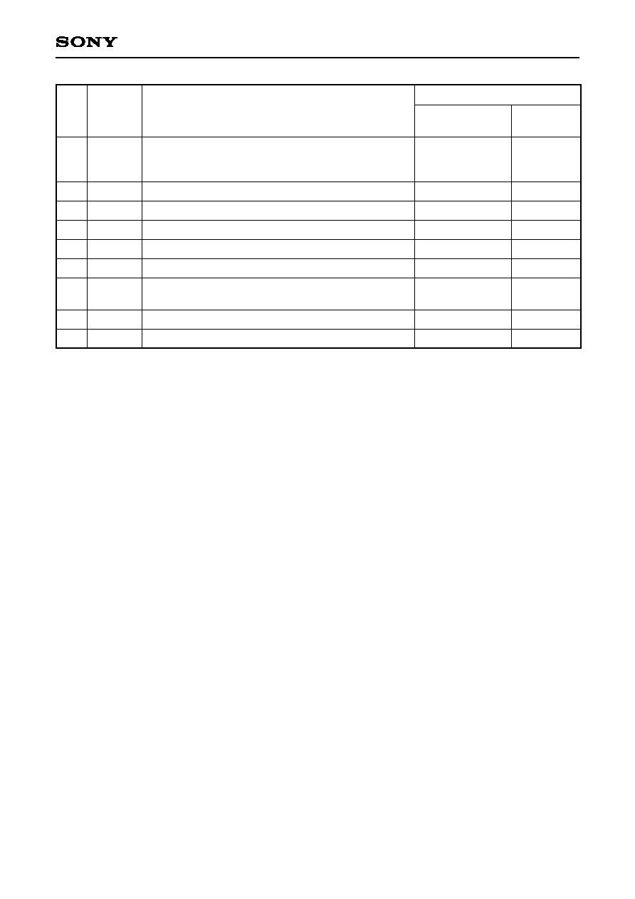
Item
Symbol
Conditions
Min.
Typ.
Max.
Unit Applicable pins
3V spec.
5V spec.
H level
L level
H level
L level
V
DD
Vcc
V
IH
V
IL
V
OH
V
OL
I
OH
= ≠4mA
I
OL
= 4mA
+BU = 3V
3.0
4.5
0.7V
DD
V
DD
≠ 0.8
1.8
5
3.3
5.0
30
3.6
5.5
5.5
0.2V
DD
0.4
3.0
70
V
V
V
V
µA
1
2, 4, 5
3
8
8
Supply voltage
Input voltage
Output voltage
Backup supply voltage
Current consumption at backup
Electrical Characteristics
(Topr = ≠40 to +85∞C)

≠ 5 ≠
GXB2000
Antenna Pre-amplifier Power Supply Circuit
1
(V
CC
)
10
(GND)
I/O connector
+3V (3/5V common specification)
RF connector
15
(1/2W)
RF part
Sony Recommend Antenna Specification
Antenna part
Center frequency
1575.42MHz
Polarization
Right handed circular polarization
Gain
≠5dBi or more (5∞
Angle of elevation)
Axis ratio
3dB typ. (Angle of elevation = 90∞)
Pre-amplifier part
Gain
22dB or more (without cable loss)
Noise figure (NF)
2.5dB or less
All-round specification (antenna + pre-anplifire + cable loss)
Gain
17dBi or more (Angle of elevation = 90∞)
Output impedance
50
Output VSWR
2.0 or less
Supply voltage
2.8 to 3.2V
Current consumption
30mA or less

≠ 6 ≠
GXB2000
Reception Unit Initialization and Operation
The GXB2000 operation is started by setting the reset input signal RESET (Pin 2) for the reception unit
initialization to high level. The timing should satisfy the conditions noted below.
During Power-on (power-on reset)
V
DD
= 3.0 to 3.6V, V
CC
= 4.5 to 5.5V, temperature = ≠40 to +85∞C
Initialization During Operation
V
DD
= 3.0 to 3.6V, V
CC
= 4.5 to 5.5V, temperature = ≠40 to +85∞C
V
DD
/V
CC
RESET (Pin 2)
V
DD
or V
CC
/2
GND
Power
supply
100ms or more
V
DD
/V
CC
RESET (Pin 2)
V
DD
or V
CC
/2
GND
Power supply
100
µ
s or more
≠ 7 ≠
GXB2000
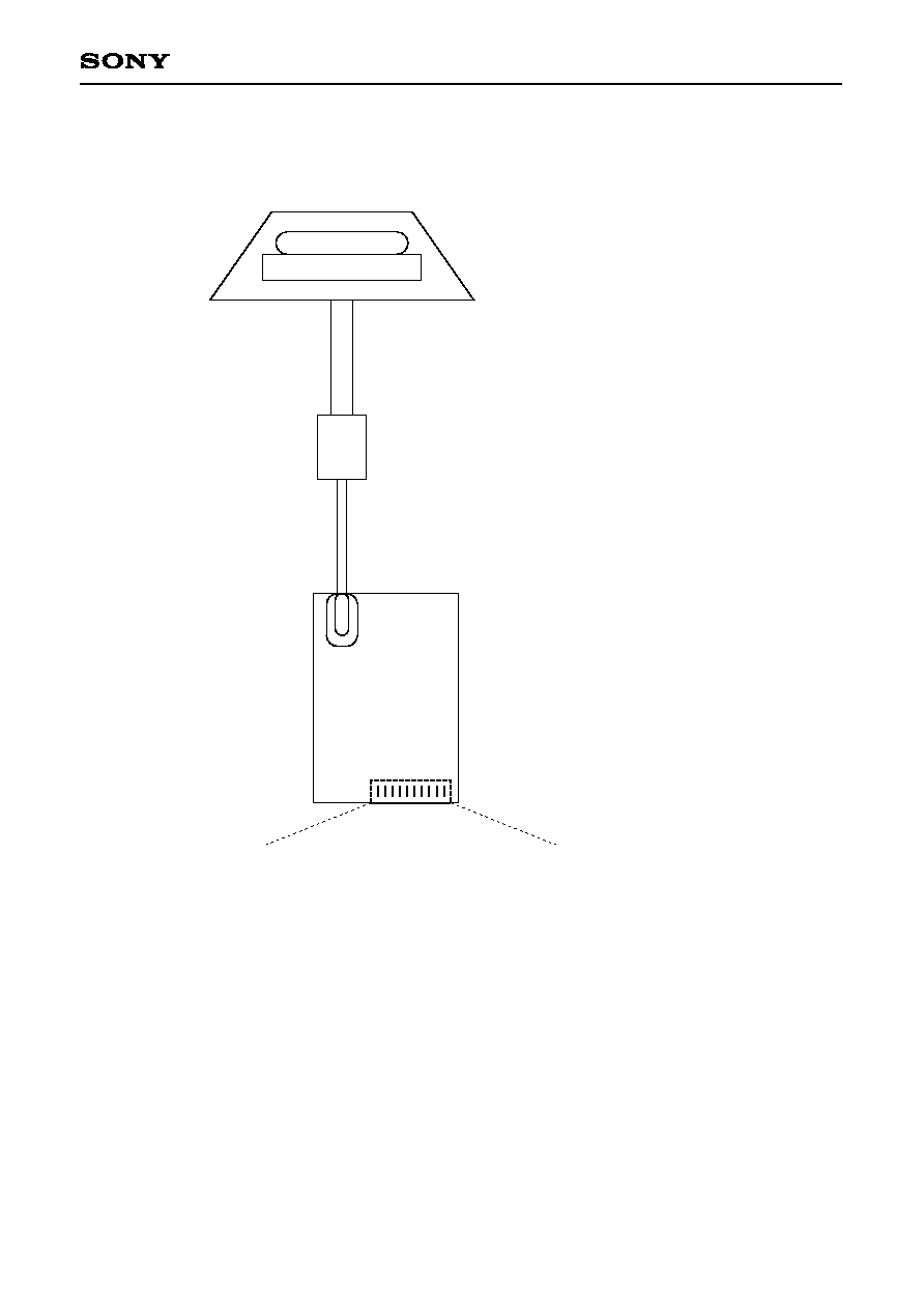
Antenna part
GPS antenna
Pre-amplifier part
RF cable with CN connector
Coaxial cable
GXB2000
GPS reception unit
I/O connector
SM10B-SRSS (JST)
Do not connect
anything to NC.
V
c
c
-
-
1
R
E
S
E
T
-
-
2
T
X
D
0
-
-
3
R
X
D
0
-
-
4
R
X
D
1
-
-
5
M
O
D
E
-
-
6
N
C
-
-
7
+
B
U
-
-
8
N
C
-
-
9
G
N
D
-
-
1
0
Fixed H level
GXB2000 GPS Reception Unit Composition
≠ 8 ≠
GXB2000
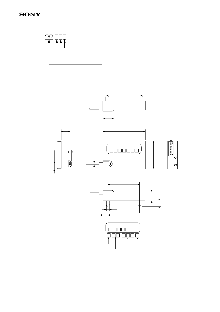
Specification of form name
GXB20 - C
Advance of software: An English letter (A to Z)
Advance of hardware: An English letter (A to Z)
Supply voltage: 3V spec. = 3, 5V spec. = 5
Customer code: Figure (0 to 99)
Package Outline
Unit: mm
SM10B-SRSS
1
0
GXB2000-3AAC
1
29.2
37.9
9.0
±
0.2
7
3
.
1
2
6
.
5
2
.
0
7.0
±
0.2
1.2
±
0.2
5
.
7
±
0
.
1
1.5
4.55
GXB2000-3AAC
Year manufactured
(End of figure for Christrian era)
Assembly plant code
Consective numbers
Week manufactured
Quality of case materials: JIS63303
Electroplated tin

S-1
GXB2000
GPS Receiver
Data Input/Output Specifications
Contents
1. I/O Data Input/Output Specifications .......................................................................................................... S-2
2. D-GPS Data Input Specifications ............................................................................................................. S-16
S-2
GXB2000
1. I/O Data Input/Output Specifications
1-1. Communication
1-1-1. Serial input/output communication method
Interface:
Asynchronous serial interface (UART)
Baud rate:
9600 bps
Start bit:
1 bit
Data bits:
8 bits
Stop bit:
1 bit
Parity bit:
None
Communication control signal: None
Output period:
Approximately 1s
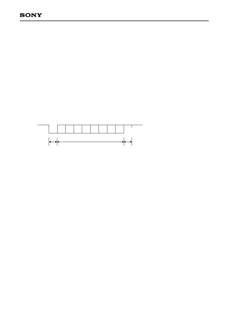
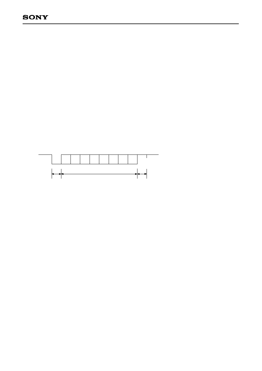
1-1-2. Asynchronous serial interface
1
LSB
MSB
Stop bit
1 bit
Start bit
1 bit
Data bits
8 bits
D0
D1
D2
D3
D4
D5
D6
D7
0

S-3
GXB2000
1-2. Output Data
1-2-1. Standard output
No.
BIT
76543210
Contents
Example
Setting value
Output data
(HEX)
1
2
3
4
5
6
7
8
9
10
11
12
13
14
15
16
17
18
19
20
21
22
23
24
25
26
27
28
29
30
31
32
33
34
11010000
0xxxxxxx
0xxxxxxx
0xxxxxxx
0xxxxxxx
0xxxxxxx
0xxxxxxx
0xxxxxxx
0xxxxxxx
0xxxxxxx
0xxxxxxx
0xxxxxxx
0xxxxxxx
0xxxxxxx
0xxxxxxx
0xxxxxxx
0xxxxxxx
0xxxxxxx
0xxxxxxx
0xxxxxxx
0xxxxxxx
0xxxxxxx
0xxxxxxx
0xxxxxxx
0xxxxxxx
0xxxxxxx
0xxxxxxx
0xxxxxxx
0xxxxxxx
0xxxxxxx
0xxxxxxx
0xxxxxxx
0xxxxxxx
0xxxxxxx
Header
Software version information
Latitude
Resolution: 0.01"
South latitude is two's complement notation.
Value range: 32400000 to ≠32400000
Longitude
Resolution: 0.01"
West longitude is two's complement notation.
Value range: 64800000 to ≠64800000
Altitude
Resolution: 1m
Negative altitude is two's complement notation.
Value range: 8191 to ≠8191
Speed
Resolution: 0.1km/h
Value range: 0 to 5150
Direction
Resolution: 0.1∞
Value range: 0 to 3599
PDOP value
Resolution: 0.1
Value range: 0 to 999
Current time mode
0: UTC time
1: JST time
Current time
Year
Year
Month
Date
Hour
Minute
Second
Day
Measurement calculation time
Year
Year
Month
Date
Hour
Minute
Second
--
01
North latitude
87∞ 29' 10.24"
(= 314950.24")
West longitude
175∞ 42' 30.11"
(= ≠632550.11")
3775m
60.5km/h
310.7∞
51.2
1
1999
02
22
12
54
46
01
1999
02
22
12
55
30
D0
01
0F
02
26
70
61
6B
1C
1D
00
1D
3F
04
5D
18
23
04
00
01
0F
4F
02
16
0C
36
2E
01
0F
4F
02
16
0C
37
1E
S-4
GXB2000
No.
BIT
76543210
Contents
Setting value
Output data
(HEX)
35
36
37
38
39
40
41
42
43
44
45
46
47
48
49
50
51
52
53 to
59 to
65 to
71 to
0xxxxxxx
0xxxxxxx
0xxxxxxx
0xxxxxxx
0xxxxxxx
0xxxxxxx
0xxxxxxx
0xxxxxxx
0xxxxxxx
0xxxxxxx
0xxxxxxx
0xxxxxxx
0xxxxxxx
0xxxxxxx
0xxxxxxx
0xxxxxxx
0xxxxxxx
0xxxxxxx
Number of visible satellites
Value range: 0 to 32
Satellite Nos. used for measurement
8 satellite Nos.
Value range: 0 to 32
Satellite No.: 0 is invalid.
Measurement calculation mode
0: Invalid
1: 2-satellite measurement
2: 3-satellite measurement
3: 4-(or more) satellite measurement
Geodesic system
Value range: 0 to 25
Measurement delay time
Resolution: 0.1s
Value range: 0 to 9
Information for 1st satellite
Satellite No.
Value range: 0 to 32
Azimuth
Resolution: 1∞
Value range: 0 to 359∞
Angle of elevation
Resolution: 1∞
Value range: 0 to 90∞
Reception status
0: Searching
1: Acquired
2: Usable for calculation
3: Radio waves cut off; interpolating
4: Satellite Unhealth
5: Currently being used for position calculation
Signal level
Resolution: 1dBHz
Value range: 0 to 100
Information for 2nd satellite
Information for 3rd satellite
Information for 4th satellite
Information for 5th satellite
8
4
10
18
9
20
25
7
31
1
18
0.4s
16
218∞
56∞
3
100
08
04
0A
12
09
14
19
07
1F
01
12
04
10
01
5A
38
03
64
Example

S-5
GXB2000
No.
BIT
76543210
Contents
Setting value
Output data
(HEX)
77 to
83 to
89 to
95 to
101 to
107 to
113 to
119 to
125 to
131 to
137 to
143 to
144 to
150
0xxxxxxx
1101101
Information for 6th satellite
Information for 7th satellite
Information for 8th satellite
Information for 9th satellite
Information for 10th satellite
Information for 11th satellite
Information for 12th satellite
Information for 13th satellite
Information for 14th satellite
Information for 15th satellite
Information for 16th satellite
Preamplifier check
0: Normal, 1: Disconnected, 2: Short circuit
Reserved
Terminator. "Z" + 80H
2
--
02
DA
Example

S-6
GXB2000
1-2-2. Expanded output
No.
BIT
76543210
Contents
Setting value
Output data
(HEX)
150
151
152
153
154
155
156
157
158
159
160
161
162
163
164
165
166
167
168
169
170
171
172
173
0xxxxxxx
0xxxxxxx
0xxxxxxx
0xxxxxxx
0xxxxxxx
0xxxxxxx
0xxxxxxx
0xxxxxxx
0xxxxxxx
0xxxxxxx
0xxxxxxx
0xxxxxxx
0xxxxxxx
0xxxxxxx
0xxxxxxx
0xxxxxxx
0xxxxxxx
0xxxxxxx
0xxxxxxx
0xxxxxxx
0xxxxxxx
0xxxxxxx
0xxxxxxx
0xxxxxxx
Latitude
0.001 to 0.0001" value
Value range: 0 to 99
Longitude
0.001 to 0.0001" value
Value range: 0 to 99
Speed
0.01 km/h value
Value range: 0 to 9
Number of healthy satellites
Value range: 0 to 32
Not related to user
Not related to user
Not related to user
SVACC
Value range: 0 to 15
Error major axis radius (1
estimated error)
Resolution: 1m
Value range: 0 to 510
Error minor axis radius (1
estimated error)
Resolution: 1m
Value range: 0 to 510
Error major axis inclination
Resolution: 1∞
Value range: 0 to 179
Angle clockwise from north
HDOP value
Resolution: 0.1
Value range: 0 to 999
VDOP value
Resolution: 0.1
Value range: 0 to 999
D-GPS measurement flag
0: Invalid
1: GPS measurement
2: D-GPS measurement
D-GPS station No.
Value range: 0 to 1023
D-GPS data elapsed time
Resolution: 1s
0.0025"
0.0091"
0.03km/h
15
--
--
--
13
130
41
165
51.2
51.2
1
1023
1
19
5B
03
0F
--
--
--
0D
01
02
00
29
01
25
04
00
04
00
01
07
7F
01
Example
S-7
GXB2000
No.
BIT
76543210
Contents
Setting value
Output data
(HEX)
174
175
176
177
178
179
180
181
182 to
190
0xxxxxxx
0xxxxxxx
0xxxxxxx
0xxxxxxx
0xxxxxxx
0xxxxxxx
0xxxxxxx
0xxxxxxx
1101101
DARC/RTCM mode
0: DARC
1: RTCM
PDOP limit value when D-GPS is on
HDOP limit value when D-GPS is on
PDOP limit value when D-GPS is off
HDOP limit value when D-GPS is off
Angle of elevation limit value
Speed limit value
Reserved
Terminator. "Z" + 80H
1
1
1
1
1
1
1
--
01
01
01
01
01
01
00
01
DA
Example
S-8
GXB2000
1-2-3. Almanac data output
No.
BIT
76543210
Contents
Setting value
Output data
(HEX)
1
2
∑
∑
∑
∑
∑
44
45
10100100
0xxxxxxx
∑
∑
∑
∑
∑
0xxxxxxx
11011010
Header
Terminator. "Z" + 80H
--
A4
DA
Example
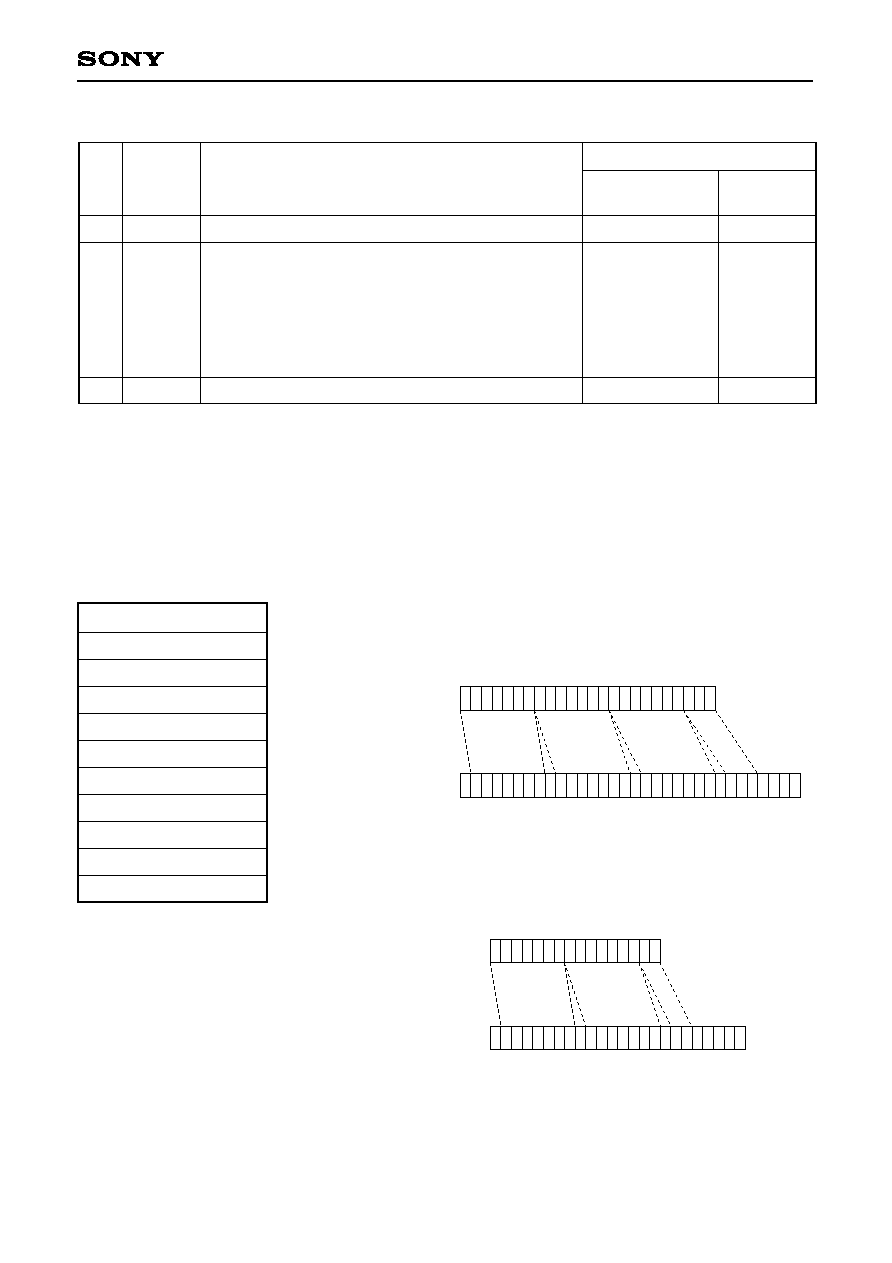
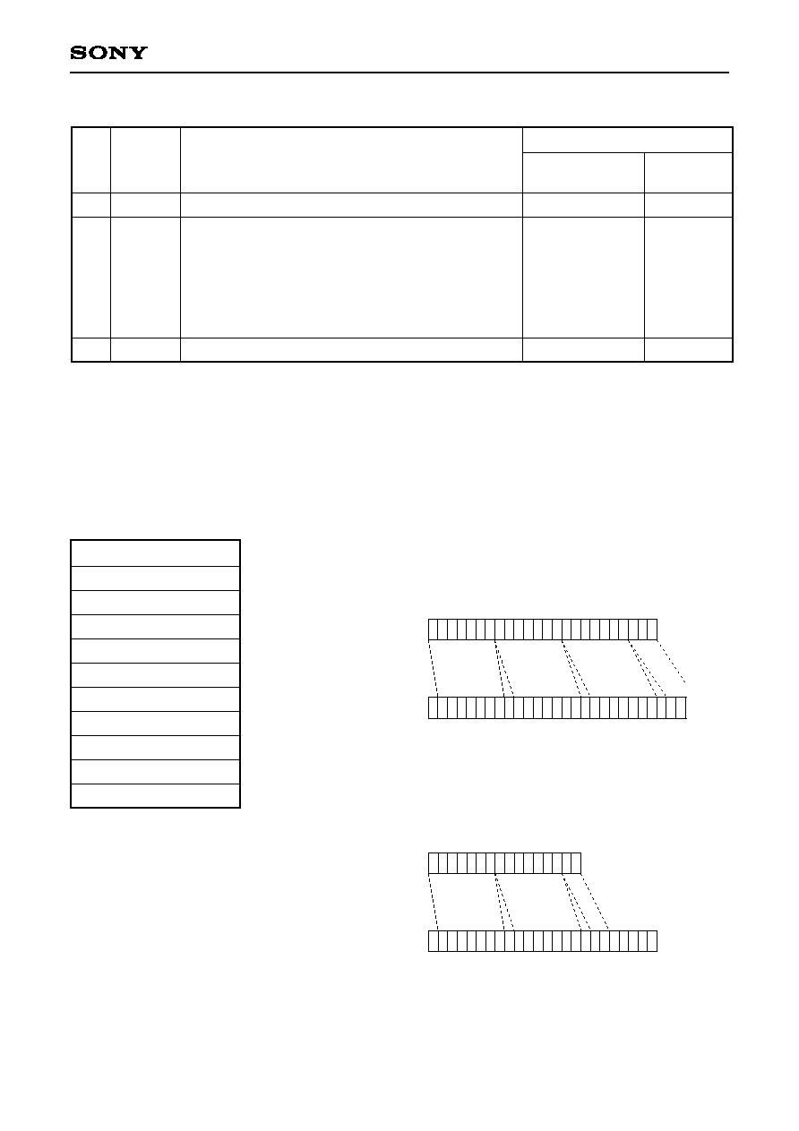
After the receiver receives an almanac output request, it transmits a response and then outputs the almanac
data. The above format is for 1 subframe of the almanac data, and 64 frames of this data are sent in
succession. Almanac communication data is sent by dividing the original data into 7-bit sections.
The almanac data stored in the GPS receiver memory has the configuration shown below. Normally each word
of the almanac data has 6-bit parity, but this is eliminated when the data is stored in the memory. In addition, a
16-bit checksum is added in consideration of communication.
WORD1
24 bits
WORD2
24 bits
WORD3
24 bits
WORD4
24 bits
WORD5
24 bits
WORD6
24 bits
WORD7
24 bits
WORD8
24 bits
WORD9
24 bits
WORD10
24 bits
Checksum
16 bits
The relationship between the above
data and the communication data is
shown to the right.
(1) Relationship between word data and communication data
23
Before conversion
After conversion
31
0
0
0
0
0
0 0 0 0
0
15
Before conversion
After conversion
23
0
0
0
0
0 0 0 0 0
0
(2) Relationship between checksum and communication data

S-9
GXB2000
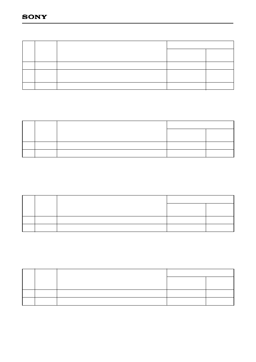
1-3. Input Data
1-3-1. TM command (receiver clock setting)
No.
BIT
76543210
Contents
Setting value
Input data
(HEX)
1
2
3
4
5
6
7
8
9
10100000
0xxxxxxx
0xxxxxxx
0xxxxxxx
0xxxxxxx
0xxxxxxx
0xxxxxxx
0xxxxxxx
11011010
Header
Year
Month
Date
Hour
Minute
Second
Terminator. "Z" + 80H
--
1999
10
29
8
46
59
--
A0
0F
4F
0A
1D
08
2E
3B
DA
Example
No.
BIT
76543210
Contents
Setting value
Input data
(HEX)
1
2
3
4
5
6
7
8
9
10
10100001
0xxxxxxx
0xxxxxxx
0xxxxxxx
0xxxxxxx
0xxxxxxx
0xxxxxxx
0xxxxxxx
0xxxxxxx
11011010
Header
Latitude
Resolution: 0.01"
South latitude is two's complement notation.
Value range: 32400000 to ≠32400000
Longitude
Resolution: 0.01"
West longitude is two's complement notation.
Value range: 64800000 to ≠64800000
Terminator. "Z" + 80H
--
North latitude
87∞ 29' 10.24"
(= 314950.24")
West longitude
175∞ 42' 30.11"
(= ≠632550.11")
--
A1
0F
02
26
70
61
6B
1C
1D
DA
Example
After receiving the above command, the GPS side sends this command as a response.
1-3-2. PT command (receiver latitude and longitude initial value settings)
After receiving the above command, the GPS side sends this command as a response.
S-10
GXB2000
1-3-3. SK command (receiver geodesic system parameter setting)
No.
BIT
76543210
Contents
Setting value
Input data
(HEX)
1
2
3
10100010
0xxxxxxx
11011010
Header
Geodesic system
Value range: 0 to 25
Terminator. "Z" + 80H
--
18
--
A2
12
DA
Example
After receiving the above command, the GPS side sends this command as a response.
1-3-4. AMI command (receive almanac data)
No.
BIT
76543210
Contents
Setting value
Input data
(HEX)
1
2
10100011
11011010
Header
Terminator. "Z" + 80H
--
--
A3
DA
Example
No.
BIT
76543210
Contents
Setting value
Input data
(HEX)
1
2
10100100
11011010
Header
Terminator. "Z" + 80H
--
--
A4
DA
Example
After receiving the above command, the GPS side sends this command as a response. The NAVI (PC) side
receives this command and then sends the almanac data to the GPS side.
1-3-5. AMO command (transmit almanac data)
After receiving the above command, the GPS side sends this command as a response, followed by the
almanac data.
1-3-6. CD command (initialize almanac data area and cold start)
No.
BIT
76543210
Contents
Setting value
Input data
(HEX)
1
2
10100101
11011010
Header
Terminator. "Z" + 80H
--
--
A5
DA
Example
After receiving the above command, the GPS side sends this command as a response.

S-11
GXB2000
1-3-7. SR command (wait 400ms and hot start)
No.
BIT
76543210
Contents
Setting value
Input data
(HEX)
1
2
10100110
11011010
Header
Terminator. "Z" + 80H
--
--
A6
DA
Example
No.
BIT
76543210
Contents
Setting value
Input data
(HEX)
1
2
3
10100111
0xxxxxxx
11011010
Header
Angle of elevation
Resolution: 1∞
Value range: 0 to 90∞
Terminator. "Z" + 80H
--
56∞
--
A7
38
DA
Example
After receiving the above command, the GPS side sends this command as a response.
1-3-8. EL command (angle of elevation limit value setting)
After receiving the above command, the GPS side sends this command as a response.
1-3-9. BC command (clear DARC receive data)
No.
BIT
76543210
Contents
Setting value
Input data
(HEX)
1
2
10101000
11011010
Header
Terminator. "Z" + 80H
--
--
A8
DA
Example
After receiving the above command, the GPS side sends this command as a response.
1-3-10. DG command (D-GPS on/off setting)
No.
BIT
76543210
Contents
Setting value
Input data
(HEX)
1
2
3
10101001
0xxxxxxx
11011010
Header
D-GPS on/off setting
0: Off
1: On
Terminator. "Z" + 80H
--
1
--
A9
01
DA
Example
After receiving the above command, the GPS side sends this command as a response.

S-12
GXB2000
1-3-11. GS command (4 DOP threshold value settings)
No.
BIT
76543210
Contents
Setting value
Input data
(HEX)
1
2
3
4
5
6
10101010
0xxxxxxx
0xxxxxxx
0xxxxxxx
0xxxxxxx
11011010
Header
PDOP threshold value when D-GPS is on
HDOP threshold value when D-GPS is on
PDOP threshold value when D-GPS is off
HDOP threshold value when D-GPS is off
Terminator. "Z" + 80H
--
64
50
64
50
--
AA
40
32
40
32
DA
Example
After receiving the above command, the GPS side sends this command as a response.
1-3-12. DMD command (DARC data input mode)
No.
BIT
76543210
Contents
Setting value
Input data
(HEX)
1
2
10101011
11011010
Header
Terminator. "Z" + 80H
--
--
AB
DA
Example
No.
BIT
76543210
Contents
Setting value
Input data
(HEX)
1
2
10101100
11011010
Header
Terminator. "Z" + 80H
--
--
AC
DA
Example
After receiving the above command, the GPS side sends this command as a response.
1-3-13. DMR command (RTCM data input mode)
After receiving the above command, the GPS side sends this command as a response.
S-13
GXB2000
No.
BIT
76543210
Contents
Setting value
Input data
(HEX)
1
2
3
10101101
0xxxxxxx
11011010
Header
Expanded output on/off setting
0: Off
1: On
Terminator. "Z" + 80H
--
1
--
AD
01
DA
Example
No.
BIT
76543210
Contents
Setting value
Input data
(HEX)
1
2
3
10101111
0xxxxxxx
11011010
Header
Current time mode setting
0: UTC
1: JST
Terminator. "Z" + 80H
--
1
--
AF
01
DA
Example
After receiving the above command, the GPS side sends this command as a response.
1-3-15. SW command (eliminate ephemeris and warm start)
1-3-14. EX command (expanded output mode on/off)
No.
BIT
76543210
Contents
Setting value
Input data
(HEX)
1
2
10101110
11011010
Header
Terminator. "Z" + 80H
--
--
AE
DA
Example
After receiving the above command, the GPS side sends this command as a response.
1-3-16. TC command (current time mode setting)
After receiving the above command, the GPS side sends this command as a response.

S-14
GXB2000
No.
BIT
76543210
Contents
Setting value
Input data
(HEX)
1
2
3
4
5
6
7
8
9
10
11
12
13
14
15
16
17
18
11000000
0xxxxxxx
0xxxxxxx
0xxxxxxx
0xxxxxxx
0xxxxxxx
0xxxxxxx
0xxxxxxx
0xxxxxxx
0xxxxxxx
0xxxxxxx
0xxxxxxx
0xxxxxxx
0xxxxxxx
0xxxxxxx
0xxxxxxx
0xxxxxxx
11011010
Header
Satellite Nos. for 16 channels
Value range: 1 to 64
0 is invalid.
Terminator. "Z" + 80H
--
9
5
18
1
20
2
6
12
--
--
--
--
--
--
--
--
--
C0
09
05
12
01
14
02
06
0C
--
--
--
--
--
--
--
--
DA
Example
After receiving the above command, the GPS side sends this command as a response.
1-3-18. LF command (D-GPS valid time setting)
1-3-17. CH command (satellite No. setting during manual setting)
No.
BIT
76543210
Contents
Setting value
Input data
(HEX)
1
2
3
4
11000111
0xxxxxxx
0xxxxxxx
11011010
Header
D-GPS valid time
Resolution: s
Terminator. "Z" + 80H
--
--
C7
DA
After receiving the above command, the GPS side sends this command as a response.
1-3-19. EP1 command (receive ephemeris data)
No.
BIT
76543210
Contents
Setting value
Input data
(HEX)
1
2
11001101
11011010
Header
Terminator. "Z" + 80H
--
--
CD
DA
Example
After receiving the above command, the GPS side sends this command as a response. The NAVI (PC) side
receives this command and then sends the ephemeris data to the GPS side.
Example

S-15
GXB2000
1-3-20. EP0 command (transmit ephemeris data)
No.
BIT
76543210
Contents
Setting value
Input data
(HEX)
1
2
3
4
10110001
0xxxxxxx
0xxxxxxx
11011010
Header
Heading filter value
Resolution: 0.1km/h
Terminator. "Z" + 80H
--
999
(99.9km/h)
--
B2
07
67
DA
After receiving the above command, the GPS side sends this command as a response, followed by the
ephemeris data.
1-3-21. VF command (heading filter value setting)
No.
BIT
76543210
Contents
Setting value
Input data
(HEX)
1
2
11001110
11011010
Header
Terminator. "Z" + 80H
--
--
CE
DA
Example
After receiving the above command, the GPS side sends this command as a response.
Example

S-16
GXB2000
2. D-GPS Data Input Specifications
2-1. Communication
2-1-1. Serial input communication method
Interface:
Asynchronous serial interface (UART)
Baud rate:
9600 bps
Start bit:
1 bit
Data bits:
8 bits
Stop bit:
1 bit
Parity bit:
None
Communication control signal: None
Input period:
1s or more
2-1-2. Asynchronous serial interface
1
LSB
MSB
Stop bit
1 bit
Start bit
1 bit
Data bits
8 bits
D0
D1
D2
D3
D4
D5
D6
D7
0

S-17
GXB2000
2-2. RTCM Data Input
RTCM data input conforms to the RTCM SC-104 format and supports message type 1.
The message type shared header and message type 1 format are shown below. These data are sent in the "6
of 8" format. In this format, each word is divided into 6-bit units, the bits are reordered so that the LSB comes
first and the MSB comes last, and then "01" is added to the head of the bits.
2-2-1. Message type shared header
PREAMBLE
STATION ID
PARITY
6bit
10bit
6bit
8bit
30
1
30
1
WORD1
MESSAGE
TYPE
MODIFIED Z-COUNT
PARITY
STATION HEALTH
SEQ NCE NO.
LENGTH OF FRAME
6bit
3bit
5bit
3bit
13bit
WORD2
PREAMBLE:
Preamble
MESSAGE TYPE:
Message type
STATION ID:
Reference station ID No.
PARITY:
Error correction code
MODIFIED Z-COUNT:
Modified Z-count
SEQ NCE NO.:
Frame sequence No.
LENGTH OF FRAME:
Frame length
STATION HEALTH:
Reference station health

S-18
GXB2000
2-2-2. Message type 1 (differential GPS correction value)
SATELLITE ID
UDRE
SCALE FACTOR
PSEUDORANGE
CORRECTION
PARITY
6bit
16bit
5bit
1bit
2bit
30
1
30
1
WORD3
RANGE-RATE
CORRECTION
ISSUE OF
DATA
PARITY
SATELLITE ID
SCALE FACTOR
UDRE
6bit
6bit
2bit
1bit
8bit
8bit
WORD4
WORD5
30
1
ISSUE OF
DATA
SATELLITE ID
PARITY
6bit
8bit
5bit
2bit
1bit
8bit
WORD6
SCALE FACTOR
PSEUDORANGE CORRECTION
(UPPER BYTE)
UDRE
30
1
RANGE-RATE
CORRECTION
PARITY
PSEUDORANGE
CORRECTION
6bit
8bit
16bit
SCALE FACTOR:
Pseudorange correction value scale factor
UDRE:
User differential range error index
SATELLITE ID:
Satellite ID No.
PSEUDORANGE CORRECTION: Pseudorange correction value
RANGE-RATE CORRECTION:
Pseudorange rate-of-change correction value
ISSUE OF DATA:
Data issue No.

S-19
GXB2000
ISSUE OF
DATA
PARITY
6bit
8bit
8bit
8bit
30
1
WORD7
RANGE-RATE
CORRECTION
ISSUE OF
DATA
PARITY
FILL
6bit
8bit
8bit
8bit
30
1
WORD8
RANGE-RATE
CORRECTION
ISSUE OF
DATA
PARITY
FILL
6bit
16bit
8bit
30
1
WORD9
PSEUDORANGE CORRECTION
(LOWER BYTE)
FILL: Dummy bit

S-20
GXB2000
2-3. DARC Data Input
DARC data is output in the communication format noted below. The D-GPS basic data is located in the D-GPS
segments. The D-GPS basic data is comprised of 288 bits (36 bytes).
The D-GPS basic data configuration is as follows.
The GPS satellite correction data configuration is as follows.
Data packet 1
22 bytes
Data packet 2
22 bytes
Checksum
1 byte
Terminator
1 byte
Prefix
4 bytes
Bit position
1 to 3
4
5 to 38
39 to 72
73 to 106
107 to 140
141 to 174
175 to 208
209 to 242
243 to 276
277 to 288
Description
D-GPS data ID
Correction time
1st GPS satellite correction data
2nd GPS satellite correction data
3rd GPS satellite correction data
4th GPS satellite correction data
5th GPS satellite correction data
6th GPS satellite correction data
7th GPS satellite correction data
8th GPS satellite correction data
Communication data
Number of bits
3 bits
1 bit
34 bits
34 bits
34 bits
34 bits
34 bits
34 bits
34 bits
34 bits
12 bits
D-GPS
segment
18 bytes
Prefix
2 bytes
D-GPS
segment
18 bytes
CRC
2 byte
xxh
0Dh
Bit position
1
2 to 3
4 to 8
9 to 19
20 to 26
27 to 34
Description
Scale factor
UDRE (User differential range error index)
GPS satellite ID
PRC (Pseudorange correction value)
RRC (Pseudorange rate-of-change correction value)
IODE (Ephemeris data issue No.)
Number of bits
1 bit
2 bits
5 bits
11 bits
7 bits
8 bits

S-21
GXB2000
Geodetic System and Corresponding Country
Setting
value
Japan, Korea
Ethiopia, Mali, Senegal, Sudan
Botswana, Lesotho, Malawi, Swaziland, Zaire, Zambia,
Zimbabwe
South Africa
Morocco
Hong Kong
Singapore
Philippines
Thailand, Vietnam
Bangladesh, India, Nepal
West Malaysia, Singapore
Belize, Costa Rica, El Salvador, Guatemala,
Honduras, Nicaragua, Mexico
Austria, Belgium, Cyprus, Channel Islands, Denmark,
England, Finland, France, Germany, Gibraltar, Greece,
Ireland, Italy, Luxembourg, Netherlands, Norway,
Portugal, Scotland, Shetland Island, Spain, Sweden,
Switzerland
Ireland
England, Isle of Man, Scotland, Shetland IsIand, Wales
Masirash Island, Oman, United Arab Emirates
Saudi Arabia
Egypt
Canada, Newfoundland Island
Alaska, Canada, Mexico, Central America,
United States of America
Australia, Tasmania Island
New Zealand
Bolivia, Chile, Colombia, Ecuador, Guyana, Peru,
Venezuela
Argentina, Bolivia, Brazil, Chile, Colombia, Ecuador,
Guyana, Paraguay, Peru, Trinidad and Tobago, Venezuela
Argentina
Brazil
Geodetic system
Reference Ellipsoid
0
1
2
3
4
5
6
7
8
9
10
11
12
13
14
15
16
17
18
19
20
21
22
23
24
25
WGS-84
TOKYO
ADINDAN
ARC 1950
CAPE
MERCHICH
HONG KONG 1963
SOUTH ASIA
LUZEN
INDIAN
INDIAN
KERTAU 1948
NORTH
AMERICAN 1927
EUROPEAN 1950
EUROPEAN 1950
IRELAND 1965
ORDNANCE
SURVEY OF
GREAT BRITAIN 1936
NAHRWAN
NAHRWAN
OLD EGYPTIAN
NORTH
AMERICAN 1927
NORTH
AMERICAN 1983
AUSTRALIAN
GEODETIC 1984
GEODETIC
DATUM 1949
PROVISIONAL SOUTH
AMERICAN 1956
SOUTH
AMERICAN 1969
CAMPO INCHAUSPE
CORREGO ALEGE
WGS-84
Bessel 1841
Clarke 1880
Clarke 1880
Clarke 1880
Clarke 1880
International
Modified Fisher 1960
Clarke 1866
Everest
Everest
Modified Everest
Clarke 1866
International
Modified Airy
Airy
Clarke 1880
Clarke 1880
Helmert 1906
Clarke 1866
GRS 80
Australian National
International
International
South American 1969
International
International

SS-1
GXB2000
GPS Receiver
NMEA-0183 Input/Output Specifications
Contents
1. I/O Data Input/Output Specifications . . . . . . . . . . . . . . . . . . . . . . . . . . . . . . . . . . . . . . . . . . . . . . . . . . . . SS-2
2. NMEA Output Specifications . . . . . . . . . . . . . . . . . . . . . . . . . . . . . . . . . . . . . . . . . . . . . . . . . . . . . . . . . SS-11
3. D-GPS Data Input Specifications . . . . . . . . . . . . . . . . . . . . . . . . . . . . . . . . . . . . . . . . . . . . . . . . . . . . . SS-27
SS-2
GXB2000
1. I/O Data Input/Output Specifications
1-1. Communication
1-1-1. Serial input/output communication method
Interface:
Asynchronous serial interface (UART)
I/O channel:
CH0
Baud rate:
4800bps
Start bit:
1 bit
Data bits:
8 bits
Stop bit:
1 bit
Parity bit:
None
Communication control signal: None
Output period:
Approximately 1s
1-1-2. Asynchronous serial interface
1
LSB
MSB
Stop bit
1 bit
Start bit
1 bit
Data bits
8 bits
D0
D1
D2
D3
D4
D5
D6
D7
0
SS-3
GXB2000
1-2. Almanac Data Output
No.
BIT
76543210
Contents
Setting value
Output data
(HEX)
1
2
∑
∑
∑
∑
∑
44
45
10100100
0xxxxxxx
∑
∑
∑
∑
∑
0xxxxxxx
11011010
Header
Terminator. "Z" + 80HEX
--
A4
DA
Example
After the receiver receives an almanac output request, it transmits a response and then outputs the almanac
data. The above format is for 1 subframe of the almanac data, and 64 frames of this data are sent in succession.
Almanac communication data is sent by dividing the original data into 7-bit sections.
The almanac data stored in the GPS receiver memory has the configuration shown below. Normally each word
of the almanac data has 6-bit parity, but this is eliminated when the data is stored in the memory. In addition, a
16-bit checksum is added in consideration of communication.
WORD1
24 bits
WORD2
24 bits
WORD3
24 bits
WORD4
24 bits
WORD5
24 bits
WORD6
24 bits
WORD7
24 bits
WORD8
24 bits
WORD9
24 bits
WORD10
24 bits
Checksum
16 bits
The relationship between the above
data and the communication data is
shown to the right.
(1) Relationship between word data and communication data
23
Before conversion
After conversion
31
0
0
0
0
0
15
Before conversion
After conversion
23
0
0
0
0
0 0 0 0 0
0
(2) Relationship between checksum and communication data
SS-4
GXB2000
1-3. Input Commands
1-3-1. TM command (receiver clock setting)
No.
BIT
76543210
Contents
Setting value
Input data
(HEX)
1
2
3
4
5
6
7
8
9
10100000
0xxxxxxx
0xxxxxxx
0xxxxxxx
0xxxxxxx
0xxxxxxx
0xxxxxxx
0xxxxxxx
11011010
Header
Year
Month
Date
Hour
Minute
Second
Terminator. "Z" + 80HEX
--
1999
10
29
8
46
59
--
A0
0F
4F
0A
1D
08
2E
3B
DA
Example
No.
BIT
76543210
Contents
Setting value
Input data
(HEX)
1
2
3
4
5
6
7
8
9
10
10100001
0xxxxxxx
0xxxxxxx
0xxxxxxx
0xxxxxxx
0xxxxxxx
0xxxxxxx
0xxxxxxx
0xxxxxxx
11011010
Header
Latitude
Resolution: 0.01"
South latitude is two's complement notation.
Value range: 32400000 to ≠32400000
Longitude
Resolution: 0.01"
West longitude is two's complement notation.
Value range: 64800000 to ≠64800000
Terminator. "Z" + 80HEX
--
North latitude
87∞ 29' 10.24"
(= ≠314950.24")
West longitude
175∞ 42' 30.11"
(= ≠632550.11")
--
A1
0F
02
26
70
61
6B
1C
1D
DA
Example
After receiving the above command, the GPS side sends this command as a response.
1-3-2. PT command (receiver latitude and longitude initial value settings)
After receiving the above command, the GPS side sends this command as a response.

SS-5
GXB2000
1-3-3. SK command (receiver geodesic system parameter setting)
No.
BIT
76543210
Contents
Setting value
Input data
(HEX)
1
2
3
10100010
0xxxxxxx
11011010
Header
Geodesic system
Value range: 0 to 25
Terminator. "Z" + 80HEX
--
18
--
A2
12
DA
Example
After receiving the above command, the GPS side sends this command as a response.
1-3-4. AMI command (receive almanac data)
No.
BIT
76543210
Contents
Setting value
Input data
(HEX)
1
2
10100011
11011010
Header
Terminator. "Z" + 80HEX
--
--
A3
DA
Example
No.
BIT
76543210
Contents
Setting value
Input data
(HEX)
1
2
10100100
11011010
Header
Terminator. "Z" + 80HEX
--
--
A4
DA
Example
After receiving the above command, the GPS side sends this command as a response. The NAVI (PC) side
receives this command and then sends the almanac data to the GPS side.
1-3-5. AMO command (transmit almanac data)
After receiving the above command, the GPS side sends this command as a response, followed by the almanac
data.
1-3-6. CD command (initialize almanac data area and cold start)
No.
BIT
76543210
Contents
Setting value
Input data
(HEX)
1
2
10100101
11011010
Header
Terminator. "Z" + 80HEX
--
--
A5
DA
Example
After receiving the above command, the GPS side sends this command as a response.

SS-6
GXB2000
1-3-7. SR command (wait 400ms and hot start)
No.
BIT
76543210
Contents
Setting value
Input data
(HEX)
1
2
10100110
11011010
Header
Terminator. "Z" + 80HEX
--
--
A6
DA
Example
No.
BIT
76543210
Contents
Setting value
Input data
(HEX)
1
2
3
10100111
0xxxxxxx
11011010
Header
Angle of elevation
Resolution: 1∞
Value range: 0 to 90∞
Terminator. "Z" + 80HEX
--
56∞
--
A7
38
DA
Example
After receiving the above command, the GPS side sends this command as a response.
1-3-8. EL command (angle of elevation limit value setting)
After receiving the above command, the GPS side sends this command as a response.
1-3-9. BC command (clear DARC receive data)
No.
BIT
76543210
Contents
Setting value
Input data
(HEX)
1
2
10101000
11011010
Header
Terminator. "Z" + 80HEX
--
--
A8
DA
Example
After receiving the above command, the GPS side sends this command as a response.
1-3-10. DG command (D-GPS on/off setting)
No.
BIT
76543210
Contents
Setting value
Input data
(HEX)
1
2
3
10101001
0xxxxxxx
11011010
Header
D-GPS on/off setting
0: Off
1: On
Terminator. "Z" + 80HEX
--
1
--
A9
01
DA
Example
After receiving the above command, the GPS side sends this command as a response.
SS-7
GXB2000
1-3-11. GS command (4 DOP threshold value settings (up to 99 (63HEX) max.))
No.
BIT
76543210
Contents
Setting value
Input data
(HEX)
1
2
3
4
5
6
7
8
9
10
10101010
0xxxxxxx
0xxxxxxx
0xxxxxxx
0xxxxxxx
0xxxxxxx
0xxxxxxx
0xxxxxxx
0xxxxxxx
11011010
Header
PDOP threshold value when D-GPS is on
HDOP threshold value when D-GPS is on
PDOP threshold value when D-GPS is off
HDOP threshold value when D-GPS is off
Terminator. "Z" + 80HEX
--
64
50
135
114
--
AA
00
40
00
32
01
07
00
72
DA
Example
After receiving the above command, the GPS side sends this command as a response.
1-3-12. DMD command (DARC data input mode)
No.
BIT
76543210
Contents
Setting value
Input data
(HEX)
1
2
10101011
11011010
Header
Terminator. "Z" + 80HEX
--
--
AB
DA
Example
No.
BIT
76543210
Contents
Setting value
Input data
(HEX)
1
2
10101100
11011010
Header
Terminator. "Z" + 80HEX
--
--
AC
DA
Example
After receiving the above command, the GPS side sends this command as a response.
1-3-13. DMR command (RTCM data input mode)
After receiving the above command, the GPS side sends this command as a response.
SS-8
GXB2000
No.
BIT
76543210
Contents
Setting value
Input data
(HEX)
1
2
3
10101101
0xxxxxxx
11011010
Header
Expanded output on/off setting
0: Off
1: On
Terminator. "Z" + 80HEX
--
1
--
AD
01
DA
Example
No.
BIT
76543210
Contents
Setting value
Input data
(HEX)
1
2
3
10101111
0xxxxxxx
11011010
Header
Current time mode setting
0: UTC
1: JST
Terminator. "Z" + 80HEX
--
1
--
AF
01
DA
Example
After receiving the above command, the GPS side sends this command as a response.
1-3-15. SW command (eliminate ephemeris and warm start)
1-3-14. EX command (expanded output mode on/off)
No.
BIT
76543210
Contents
Setting value
Input data
(HEX)
1
2
10101110
11011010
Header
Terminator. "Z" + 80HEX
--
--
AE
DA
Example
After receiving the above command, the GPS side sends this command as a response.
1-3-16. TC command (current time mode setting)
After receiving the above command, the GPS side sends this command as a response.

SS-9
GXB2000
No.
BIT
76543210
Contents
Setting value
Input data
(HEX)
1
2
3
4
5
6
7
8
9
10
11
12
13
14
15
16
17
18
11000000
0xxxxxxx
0xxxxxxx
0xxxxxxx
0xxxxxxx
0xxxxxxx
0xxxxxxx
0xxxxxxx
0xxxxxxx
0xxxxxxx
0xxxxxxx
0xxxxxxx
0xxxxxxx
0xxxxxxx
0xxxxxxx
0xxxxxxx
0xxxxxxx
11011010
Header
Satellite Nos. for 16 channels
Value range: 1 to 64
0 is invalid.
Terminator. "Z" + 80HEX
--
9
5
18
1
20
2
6
12
--
--
--
--
--
--
--
--
--
C0
09
05
12
01
14
02
06
0C
--
--
--
--
--
--
--
--
DA
Example
After receiving the above command, the GPS side sends this command as a response.
1-3-18. LF command (D-GPS valid time setting)
1-3-17. CH command (satellite No. setting during manual setting)
No.
BIT
76543210
Contents
Setting value
Input data
(HEX)
1
2
3
4
11000111
0xxxxxxx
0xxxxxxx
11011010
Header
D-GPS valid time
Resolution: s
Terminator. "Z" + 80HEX
--
--
C7
DA
After receiving the above command, the GPS side sends this command as a response.
1-3-19. EPI command (receive ephemeris data)
No.
BIT
76543210
Contents
Setting value
Input data
(HEX)
1
2
11001101
11011010
Header
Terminator. "Z" + 80HEX
--
--
CD
DA
Example
After receiving the above command, the GPS side sends this command as a response. The NAVI (PC) side
receives this command and then sends the ephemeris data to the GPS side.
Example

SS-10
GXB2000
1-3-20. EP0 command (transmit ephemeris data)
No.
BIT
76543210
Contents
Setting value
Input data
(HEX)
1
2
3
4
10110001
0xxxxxxx
0xxxxxxx
11011010
Header
Heading filter value
Resolution: 0.1km/h
Terminator. "Z" + 80HEX
--
999
(99.9km/h)
--
B2
07
67
DA
After receiving the above command, the GPS side sends this command as a response, followed by the ephemeris
data.
1-3-21. VF command (heading filter value setting)
No.
BIT
76543210
Contents
Setting value
Input data
(HEX)
1
2
11001110
11011010
Header
Terminator. "Z" + 80HEX
--
--
CE
DA
Example
After receiving the above command, the GPS side sends this command as a response.
Example

SS-11
GXB2000
No.
BIT
76543210
Contents
Setting value
Output data
(HEX)
1
2
3
4
5
6
7
8
9
10
11
12
13
14
15
16
17
18
19
20
21
22
23
24
25
26
27
28
29
30
31
32
33
34
00100100
01000111
01010000
01000111
01000111
01000001
01001100
xxxxxxxx
xxxxxxxx
xxxxxxxx
xxxxxxxx
xxxxxxxx
xxxxxxxx
01001100
xxxxxxxx
xxxxxxxx
xxxxxxxx
xxxxxxxx
00101110
xxxxxxxx
xxxxxxxx
xxxxxxxx
01001100
xxxxxxxx
01001100
xxxxxxxx
xxxxxxxx
xxxxxxxx
xxxxxxxx
xxxxxxxx
00101110
xxxxxxxx
xxxxxxxx
xxxxxxxx
Header
"$"
Address field
"G"
"P"
"G"
"G"
"A"
" , "
UTC time
Hour (10's digit)
Hour (1's digit)
Minute (10's digit)
Minute (1's digit)
Second (10's digit)
Second (1's digit)
" , "
Latitude
Degree (10's digit)
Degree (1's digit)
Minute (10's digit)
Minute (1's digit)
" . "
Minute (0.1's digit)
Minute (0.01's digit)
Minute (0.001's digit)
" , "
Latitude direction
"N" or "S"
" , "
Longitude
Degree (100's digit)
Degree (10's digit)
Degree (1's digit)
Minute (10's digit)
Minute (1's digit)
" . "
Minute (0.1's digit)
Minute (0.01's digit)
Minute (0.001's digit)
Fixed
Fixed
Fixed
06:22:43
Fixed
36∞ 03.979'
Fixed
North latitude
Fixed
140∞ 10.296'
24
47
50
47
47
41
2C
00
36
32
32
34
33
2C
33
36
30
33
2E
39
37
39
2C
4E
2C
31
34
30
31
30
2E
32
39
36
Example
2. NMEA Output Specifications
2-1. Output Messages
2-1-1. GPGGA message

SS-12
GXB2000
No.
BIT
76543210
Contents
Setting value
Output data
(HEX)
35
36
37
38
39
40
41
42
43
44
45
46
47
48
49
50
51
52
53
54
55
56
57
58
59
60
61
62
63
64
65
66
01001100
xxxxxxxx
01001100
xxxxxxxx
01001100
xxxxxxxx
xxxxxxxx
01001100
xxxxxxxx
xxxxxxxx
00101110
xxxxxxxx
01001100
xxxxxxxx
xxxxxxxx
xxxxxxxx
xxxxxxxx
01001100
01001101
01001100
01001100
01001101
01001100
xxxxxxxx
xxxxxxxx
xxxxxxxx
01001100
xxxxxxxx
xxxxxxxx
xxxxxxxx
xxxxxxxx
00101010
" , "
Longitude direction
"E" or "W"
" , "
GPS Quality Indicator
"0": Invalid
"1": GPS measurement
"2": D-GPS measurement
" , "
Number of satellites used for measurement calculation
"00" to "12"
" , "
HDOP
10's digit
1's digit
" . "
0.1's digit
" , "
Altitude (m)
1,000's digit
100's digit
10's digit
1's digit
" , "
Altitude units
"M"
" , "
" , "
"M"
" , "
D-GPS data elapsed time (s)
100's digit
10's digit
1's digit
" , "
D-GPS reference station ID
1,000's digit
100's digit
10's digit
1's digit
"
"
Fixed
West longitude
Fixed
D-GPS
measurement
Fixed
7-satellite
measurement
Fixed
1.2
Fixed
23m
Fixed
Fixed
Fixed
Fixed
Fixed
Fixed
5s
Fixed
0
Fixed
2C
57
2C
32
2C
30
37
2C
30
31
2E
32
2C
30
30
32
33
2C
4D
2C
2C
4D
2C
30
30
35
2C
30
30
30
30
2A
Example

SS-13
GXB2000
No.
BIT
76543210
Contents
Setting value
Output data
(HEX)
67
68
69
70
xxxxxxxx
xxxxxxxx
00001101
00001010
Checksum
Hexadecimal upper digits
Hexadecimal lower digits
Terminator
<CR>
<LF>
4A
Fixed
34
41
0D
0A
Example
The Geoidal Separation parameter is not output (between No. 54 and No. 55).

SS-14
GXB2000
2-1-2. GPGLL message
No.
BIT
76543210
Contents
Setting value
Output data
(HEX)
1
2
3
4
5
6
7
8
9
10
11
12
13
14
15
16
17
18
19
20
21
22
23
24
25
26
27
28
29
30
31
32
33
34
35
36
37
00100100
01000111
01010000
01000111
01001100
01001100
01001100
xxxxxxxx
xxxxxxxx
xxxxxxxx
xxxxxxxx
00101110
xxxxxxxx
xxxxxxxx
xxxxxxxx
01001100
xxxxxxxx
01001100
xxxxxxxx
xxxxxxxx
xxxxxxxx
xxxxxxxx
xxxxxxxx
00101110
xxxxxxxx
xxxxxxxx
xxxxxxxx
01001100
xxxxxxxx
01001100
xxxxxxxx
xxxxxxxx
xxxxxxxx
xxxxxxxx
xxxxxxxx
xxxxxxxx
01001100
Header
"$"
Address field
"G"
"P"
"G"
"L"
"L"
" , "
Latitude
Degree (10's digit)
Degree (1's digit)
Minute (10's digit)
Minute (1's digit)
" . "
Minute (0.1's digit)
Minute (0.01's digit)
Minute (0.001's digit)
" , "
Latitude direction
"N" or "S"
" , "
Longitude
Degree (100's digit)
Degree (10's digit)
Degree (1's digit)
Minute (10's digit)
Minute (1's digit)
" . "
Minute (0.1's digit)
Minute (0.01's digit)
Minute (0.001's digit)
" , "
Longitude direction
"E" or "W"
" , "
UTC time
Hour (10's digit)
Hour (1's digit)
Minute (10's digit)
Minute (1's digit)
Second (10's digit)
Second (1's digit)
" , "
Fixed
Fixed
Fixed
36∞ 03.979'
Fixed
North latitude
Fixed
140∞ 10.296'
Fixed
West longitude
Fixed
06:22:43
Fixed
24
47
50
47
4C
4C
2C
33
36
30
33
2E
39
37
39
2C
4E
2C
31
34
30
31
30
2E
32
39
36
2C
57
2C
00
36
32
32
34
33
2C
Example
SS-15
GXB2000
No.
BIT
76543210
Contents
Setting value
Output data
(HEX)
38
39
40
41
42
43
xxxxxxxx
00101010
xxxxxxxx
xxxxxxxx
00001101
00001010
Status
"A": Data valid
"V": Data invalid
"
"
Checksum
Hexadecimal upper digits
Hexadecimal lower digits
Terminator
<CR>
<LF>
Valid
Fixed
4A
Fixed
41
2A
34
41
0D
0A
Example

SS-16
GXB2000
2-1-3. GPGSA message
No.
BIT
76543210
Contents
Setting value
Output data
(HEX)
1
2
3
4
5
6
7
8
9
10
11
12
13
14
15 to 17
18 to 20
21 to 23
24 to 26
27 to 29
30 to 32
33 to 35
36 to 38
39 to 41
42 to 44
45 to 47
48
49
50
51
52
00100100
01000111
01010000
01000111
01010011
01000001
01001100
xxxxxxxx
01001100
xxxxxxxx
01001100
xxxxxxxx
xxxxxxxx
01001100
xxxxxxxx
xxxxxxxx
00101110
xxxxxxxx
01001100
Header
"$"
Address field
"G"
"P"
"G"
"S"
"A"
" , "
GPS measurement switching mode
"M": Manual
"A": Auto
" , "
GPS measurement mode
"1": Invalid
"2": 2D measurement
"3": 3D measurement
" , "
Satellite Nos. used for measurement
1st satellite No.
10's digit
1's digit
" , "
2nd satellite No.
3rd satellite No.
4th satellite No.
5th satellite No.
6th satellite No.
7th satellite No.
8th satellite No.
9th satellite No.
10th satellite No.
11th satellite No.
12th satellite No.
PDOP
10's digit
1's digit
" . "
0.1's digit
" , "
Fixed
Fixed
Fixed
Fixed to "A"
Fixed
3D measurement
Fixed
2.4
Fixed
24
47
50
47
53
41
2C
41
2C
33
2C
30
32
2E
34
2C
Example

SS-17
GXB2000
No.
BIT
76543210
Contents
Setting value
Output data
(HEX)
53
54
55
56
57
58
59
60
61
62
63
64
65
66
xxxxxxxx
xxxxxxxx
00101110
xxxxxxxx
01001100
xxxxxxxx
xxxxxxxx
00101110
xxxxxxxx
00101010
xxxxxxxx
xxxxxxxx
00001101
00001010
HDOP
10's digit
1's digit
" . "
0.1's digit
" , "
VDOP
10's digit
1's digit
" . "
0.1's digit
"
"
Checksum
Hexadecimal upper digits
Hexadecimal lower digits
Terminator
<CR>
<LF>
1.2
Fixed
2.0
Fixed
4A
Fixed
30
31
2E
32
2C
30
32
2E
30
2A
34
41
0D
0A
Example
The data length for "Satellite Nos. used for measurement" is variable in order to output the numbers of all the
satellites used for position measurement.

SS-18
GXB2000
2-1-4. GPGSV message
No.
BIT
76543210
Contents
Setting value
Output data
(HEX)
1
2
3
4
5
6
7
8
9
10
11
12
13
14
15
16
17
18
19
20
21
22
23
24
25
26
27
28 to 40
41 to 53
54 to 56
67
68
69
00100100
01000111
01010000
01000111
01010011
01010110
01001100
xxxxxxxx
01001100
xxxxxxxx
01001100
xxxxxxxx
xxxxxxxx
01001100
xxxxxxxx
xxxxxxxx
01001100
xxxxxxxx
xxxxxxxx
01001100
xxxxxxxx
xxxxxxxx
xxxxxxxx
01001100
xxxxxxxx
xxxxxxxx
01001100
00101010
xxxxxxxx
xxxxxxxx
Header
"$"
Address field
"G"
"P"
"G"
"S"
"V"
" , "
Total number of GPGSV messages
"1" to "3"
" , "
GPGSV message number
"1" to "3"
" , "
Number of satellites within field of vision
10's digit
1's digit
" , "
Information on satellites within field of vision for four satellites
Satellite No.
10's digit
1's digit
" , "
Angle of elevation (∞)
10's digit
1's digit
" , "
Azimuth (∞)
100's digit
10's digit
1's digit
" , "
C/N (dB)
10's digit
1's digit
" , "
Information for 2nd satellite
Information for 3rd satellite
Information for 4th satellite
"
"
Checksum
Hexadecimal upper digits
Hexadecimal lower digits
Fixed
Fixed
Fixed
2
Fixed
1
Fixed
08
Fixed
Fixed
4A
24
47
50
47
53
56
2C
32
2C
31
2C
30
38
2C
2A
34
41
Example

SS-19
GXB2000
No.
BIT
76543210
Contents
Setting value
Output data
(HEX)
70
71
00001101
00001010
Terminator
<CR>
<LF>
Fixed
0D
0A
Example
The satellite information for up to four satellites can be sent with a single GPGSV message, so multiple
GPGSV messages (up to three messages) are sent when there are four or more satellites within the field of
vision. When there are fewer than four satellites, the information for that number of satellites is sent.

SS-20
GXB2000
2-1-5. GPRMC message
No.
BIT
76543210
Contents
Setting value
Output data
(HEX)
1
2
3
4
5
6
7
8
9
10
11
12
13
14
15
16
17
18
19
20
21
22
23
24
25
26
27
28
29
30
31
32
33
34
35
36
00100100
01000111
01010000
01010010
01001101
01000011
01001100
xxxxxxxx
xxxxxxxx
xxxxxxxx
xxxxxxxx
xxxxxxxx
xxxxxxxx
01001100
xxxxxxxx
01001100
xxxxxxxx
xxxxxxxx
xxxxxxxx
xxxxxxxx
00101110
xxxxxxxx
xxxxxxxx
xxxxxxxx
01001100
xxxxxxxx
01001100
xxxxxxxx
xxxxxxxx
xxxxxxxx
xxxxxxxx
xxxxxxxx
00101110
xxxxxxxx
xxxxxxxx
xxxxxxxx
Header
"$"
Address field
"G"
"P"
"R"
"M"
"C"
" , "
UTC time
Hour (10's digit)
Hour (1's digit)
Minute (10's digit)
Minute (1's digit)
Second (10's digit)
Second (1's digit)
" , "
Status
"A": Data valid
"V": Data invalid
" , "
Latitude
Degree (10's digit)
Degree (1's digit)
Minute (10's digit)
Minute (1's digit)
" . "
Minute (0.1's digit)
Minute (0.01's digit)
Minute (0.001's digit)
" , "
Latitude direction
"N" or "S"
" , "
Longitude
Degree (100's digit)
Degree (10's digit)
Degree (1's digit)
Minute (10's digit)
Minute (1's digit)
" . "
Minute (0.1's digit)
Minute (0.01's digit)
Minute (0.001's digit)
Fixed
Fixed
Fixed
06:22:43
Fixed
Valid
Fixed
36∞ 03.979'
Fixed
North latitude
Fixed
140∞ 10.296'
24
47
50
52
4D
43
2C
00
36
32
32
34
33
2C
41
2C
33
36
30
33
2E
39
37
39
2C
4E
2C
31
34
30
31
30
2E
32
39
36
Example

SS-21
GXB2000
No.
BIT
76543210
Contents
Setting value
Output data
(HEX)
37
38
39
40
41
42
43
44
45
46
47
48
49
50
51
52
53
54
55
56
57
58
59
60
61
62
63
64
01001100
xxxxxxxx
01001100
xxxxxxxx
xxxxxxxx
xxxxxxxx
00101110
xxxxxxxx
01001100
xxxxxxxx
xxxxxxxx
xxxxxxxx
00101110
xxxxxxxx
01001100
xxxxxxxx
xxxxxxxx
xxxxxxxx
xxxxxxxx
xxxxxxxx
xxxxxxxx
01001100
01001100
00101010
xxxxxxxx
xxxxxxxx
00001101
00001010
" , "
Longitude direction
"E" or "W"
" , "
Speed (knots)
100's digit
10's digit
1's digit
" . "
0.1's digit
" , "
Heading (∞)
100's digit
10's digit
1's digit
" . "
0.1's digit
" , "
Date
10's digit
1's digit
Month
10's digit
1's digit
Year
10's digit
1's digit
" , "
" , "
"
"
Checksum
Hexadecimal upper digits
Hexadecimal lower digits
Terminator
<CR>
<LF>
Fixed
West longitude
Fixed
20knot/h
Fixed
48.5∞
Fixed
July 13, 1999
Fixed
Fixed
Fixed
4A
Fixed
2C
57
2C
30
32
30
2E
30
2C
30
34
38
2E
35
2C
31
33
30
37
39
39
2C
2C
2A
34
41
0D
0A
Example
The Magnetic Variation parameter is not output.
(between No. 58 and No. 59, and between No. 59 and No. 60)

SS-22
GXB2000
2-1-6. GPVTG message
No.
BIT
76543210
Contents
Setting value
Output data
(HEX)
1
2
3
4
5
6
7
8
9
10
11
12
13
14
15
16
17
18
19
20
21
22
23
24
25
26
27
28
29
30
31
32
33
34
35
36
00100100
01000111
01010000
01010110
01010100
01000111
01001100
xxxxxxxx
xxxxxxxx
xxxxxxxx
00101110
xxxxxxxx
01001100
01010100
01001100
01001100
01001101
01001100
xxxxxxxx
xxxxxxxx
xxxxxxxx
00101110
xxxxxxxx
01001100
01001110
01001100
xxxxxxxx
xxxxxxxx
xxxxxxxx
00101110
xxxxxxxx
01001100
01001011
00101010
xxxxxxxx
xxxxxxxx
Header
"$"
Address field
"G"
"P"
"V"
"T"
"G"
" , "
Heading (∞)
100's digit
10's digit
1's digit
" . "
0.1's digit
" , "
"T"
" , "
" , "
"M"
" , "
Speed (knots)
100's digit
10's digit
1's digit
" . "
0.1's digit
" , "
"N"
" , "
Speed (km/h)
100's digit
10's digit
1's digit
" . "
0.1's digit
" , "
"K"
"
"
Checksum
Hexadecimal upper digits
Hexadecimal lower digits
Fixed
Fixed
Fixed
48.5∞
Fixed
Fixed
Fixed
Fixed
Fixed
Fixed
20knot/h
Fixed
Fixed
Fixed
20km/h
Fixed
Fixed
Fixed
4A
24
47
50
56
54
47
2C
30
34
38
2E
35
2C
54
2C
2C
4D
2C
30
32
30
2E
30
2C
4E
2C
30
32
30
2E
30
2C
4B
2A
34
41
Example

SS-23
GXB2000
No.
BIT
76543210
Contents
Setting value
Output data
(HEX)
37
38
00001101
00001010
Terminator
<CR>
<LF>
Fixed
0D
0A
Example
The Course Over Ground and Degree Magnetic parameters are not output.
(between No. 15 and No. 16)

SS-24
GXB2000
2-1-7. GPZDA message
No.
BIT
76543210
Contents
Setting value
Output data
(HEX)
1
2
3
4
5
6
7
8
9
10
11
12
13
14
15
16
17
18
19
20
21
22
23
24
25
26
27
28
29
00100100
01000111
01010000
01011010
01000100
01000001
01001100
xxxxxxxx
xxxxxxxx
xxxxxxxx
xxxxxxxx
xxxxxxxx
xxxxxxxx
01001100
xxxxxxxx
xxxxxxxx
01001100
xxxxxxxx
xxxxxxxx
01001100
xxxxxxxx
xxxxxxxx
01001100
01001100
00101010
xxxxxxxx
xxxxxxxx
00001101
00001010
Header
"$"
Address field
"G"
"P"
"Z"
"D"
"A"
" , "
UTC time
Hour (10's digit)
Hour (1's digit)
Minute (10's digit)
Minute (1's digit)
Second (10's digit)
Second (1's digit)
" , "
Date
10's digit
1's digit
" , "
Month
10's digit
1's digit
" , "
Year
10's digit
1's digit
" , "
" , "
"
"
Checksum
Hexadecimal upper digits
Hexadecimal lower digits
Terminator
<CR>
<LF>
Fixed
Fixed
Fixed
06:22:43
Fixed
13th
Fixed
July
Fixed
1999
Fixed
Fixed
Fixed
4A
Fixed
24
47
50
5A
44
41
2C
00
36
32
32
34
33
2C
31
33
2C
30
37
2C
39
39
2C
2C
2A
34
41
0D
0A
Example
The Local Zone Description parameter is not output.
(between No. 23 and No. 24, and between No. 24 and No. 25)

SS-25
GXB2000
2-1-8. PSNY message (manufacturer expanded output)
No.
BIT
76543210
Contents
Setting value
Output data
(HEX)
1
2
3
4
5
6
7
8
9
10
11
12
13
14
15
16
17
18
19
20
21
22
23
24
25
26
27
28
29
00100100
01010000
01010011
01011110
01011001
01001100
xxxxxxxx
01001100
xxxxxxxx
xxxxxxxx
01001100
xxxxxxxx
xxxxxxxx
01001100
xxxxxxxx
xxxxxxxx
xxxxxxxx
01001100
xxxxxxxx
xxxxxxxx
01001100
xxxxxxxx
xxxxxxxx
01001100
xxxxxxxx
xxxxxxxx
01001100
xxxxxxxx
xxxxxxxx
Header
"$"
Address field
"P"
"S"
"N"
"Y"
" , "
Preamplifier status
"0": Normal
"1": Open
"2": Shorted
" , "
Geodesic system
"0" to "25"
" , "
Angle of elevation limit (∞)
10's digit
1's digit
" , "
Speed limit (km/h)
100's digit
10's digit
1's digit
" , "
PDOP limit (D-GPS on)
10's digit
1's digit
" , "
HDOP limit (D-GPS on)
10's digit
1's digit
" , "
PDOP limit (D-GPS off)
10's digit
1's digit
" , "
HDOP limit (D-GPS off)
10's digit
1's digit
Fixed
Fixed
Fixed
Open
Fixed
WGS-84
Fixed
5∞
Fixed
500km/h
Fixed
4
Fixed
6
Fixed
4
Fixed
6
24
50
53
5E
49
2C
31
2C
30
30
2C
30
35
2C
35
30
30
2C
30
34
2C
30
36
2C
30
34
2C
30
36
Example
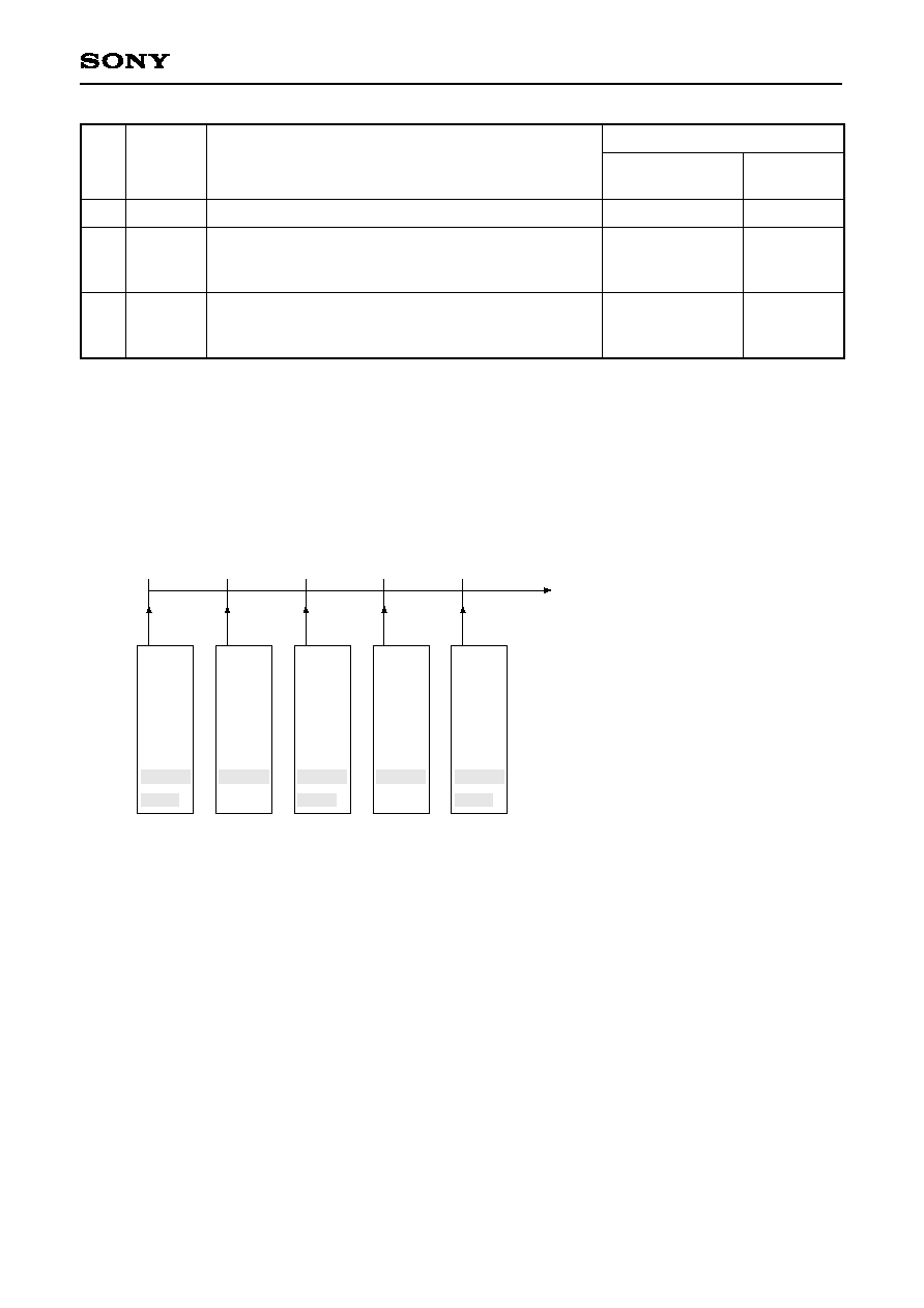
SS-26
GXB2000
No.
BIT
76543210
Contents
Setting value
Output data
(HEX)
30
31
32
33
34
00101010
xxxxxxxx
xxxxxxxx
00001101
00001010
"
"
Checksum
Hexadecimal upper digits
Hexadecimal lower digits
Terminator
<CR>
<LF>
Fixed
4A
Fixed
2A
34
41
0D
0A
Example
2-2. Output Timing
1s period: GPVTG, GPGGA, GPGLL, GPRMC, GPZDA
2s period: GPGSA, PSNY, GPGSV
GPVTG
GPGGA
GPGLL
GPRMC
GPZDA
GPGSA
PSNY
1s
GPVTG
GPGGA
GPGLL
GPRMC
GPZDA
GPGSV
2s
GPVTG
GPGGA
GPGLL
GPRMC
GPZDA
GPGSA
PSNY
3s
GPVTG
GPGGA
GPGLL
GPRMC
GPZDA
GPGSV
4s
GPVTG
GPGGA
GPGLL
GPRMC
GPZDA
GPGSA
PSNY
5s

SS-27
GXB2000
3. D-GPS Data Input Specifications
3-1. Communication
3-1-1. Serial input communication method
Interface:
Asynchronous serial interface (UART)
I/O channel:
CH1
Baud rate:
9600bps
Start bit:
1 bit
Data bits:
8 bits
Stop bit:
1 bit
Parity bit:
None
Communication control signal: None
Input period:
1s or more
3-1-2. Asynchronous serial interface
1
LSB
MSB
Stop bit
1 bit
Start bit
1 bit
Data bits
8 bits
D0
D1
D2
D3
D4
D5
D6
D7
0

SS-28
GXB2000
3-2. RTCM Data Input
RTCM data input conforms to the RTCM SC-104 format and supports message type 1.
The message type shared header and message type 1 format are shown below. These data are sent in the
"6 of 8" format. In this format, each word is divided into 6-bit units, the bits are reordered so that the LSB
comes first and the MSB comes last, and then "01" is added to the head of the bits.
3-2-1. Message type shared header
PREAMBLE
STATION ID
PARITY
6bit
10bit
6bit
8bit
30
1
30
1
WORD1
MESSAGE
TYPE
MODIFIED Z-COUNT
PARITY
STATION HEALTH
SEQ NCE NO.
LENGTH OF FRAME
6bit
3bit
5bit
3bit
13bit
WORD2
PREAMBLE:
Preamble
MESSAGE TYPE:
Message type
STATION ID:
Reference station ID No.
PARITY:
Error correction code
MODIFIED Z-COUNT: Modified Z-count
SEQ NCE NO.:
Frame sequence No.
LENGTH OF FRAME: Frame length
STATION HEALTH:
Reference station health

SS-29
GXB2000
3-2-2. Message type 1 (differential GPS correction value)
SATELLITE ID
UDRE
SCALE FACTOR
PSEUDORANGE
CORRECTION
PARITY
6bit
16bit
5bit
1bit
2bit
30
1
30
1
WORD3
RANGE-RATE
CORRECTION
ISSUE OF
DATA
PARITY
SATELLITE ID
SCALE FACTOR
UDRE
6bit
6bit
2bit
1bit
8bit
8bit
WORD4
WORD5
30
1
ISSUE OF
DATA
SATELLITE ID
PARITY
6bit
8bit
5bit
2bit
1bit
8bit
WORD6
SCALE FACTOR
PSEUDORANGE CORRECTION
(UPPER BYTE)
UDRE
30
1
RANGE-RATE
CORRECTION
PARITY
PSEUDORANGE
CORRECTION
6bit
8bit
16bit
SCALE FACTOR:
Pseudorange correction value scale factor
UDRE:
User differential range error index
SATELLITE ID:
Satellite ID No.
PSEUDORANGE CORRECTION: Pseudorange correction value
RANGE-RATE CORRECTION:
Pseudorange rate-of-change correction value
ISSUE OF DATA:
Data issue No.

SS-30
GXB2000
ISSUE OF
DATA
PARITY
6bit
8bit
8bit
8bit
30
1
WORD7
RANGE-RATE
CORRECTION
ISSUE OF
DATA
PARITY
FILL
6bit
8bit
8bit
8bit
30
1
WORD8
RANGE-RATE
CORRECTION
ISSUE OF
DATA
PARITY
FILL
6bit
16bit
8bit
30
1
WORD9
PSEUDORANGE CORRECTION
(LOWER BYTE)
FILL: Dummy bit
SS-31
GXB2000
3-3. DARC Data Input
DARC data is output in the communication format noted below. The D-GPS basic data is located in the D-GPS
segments. The D-GPS basic data is comprised of 288 bits (36 bytes).
The D-GPS basic data configuration is as follows.
The GPS satellite correction data configuration is as follows.
Data packet 1
22 bytes
Data packet 2
22 bytes
Checksum
1 byte
Terminator
1 byte
Prefix
4 bytes
Bit position
1 to 3
4
5 to 38
39 to 72
73 to 106
107 to 140
141 to 174
175 to 208
209 to 242
243 to 276
277 to 288
Description
D-GPS data ID
Correction time
1st GPS satellite correction data
2nd GPS satellite correction data
3rd GPS satellite correction data
4th GPS satellite correction data
5th GPS satellite correction data
6th GPS satellite correction data
7th GPS satellite correction data
8th GPS satellite correction data
Communication data
Number of bits
3 bits
1 bit
34 bits
34 bits
34 bits
34 bits
34 bits
34 bits
34 bits
34 bits
12 bits
D-GPS
segment
18 bytes
Prefix
2 bytes
D-GPS
segment
18 bytes
CRC
2 bytes
xxh
0Dh
Bit position
1
2 to 3
4 to 8
9 to 19
20 to 26
27 to 34
Description
Scale factor
UDRE (User differential range error index)
GPS satellite ID
PRC (Pseudorange correction value)
RRC (Pseudorange rate-of-change correction value)
IODE (Ephemeris data issue No.)
Number of bits
1 bit
2 bits
5 bits
11 bits
7 bits
8 bits