
SAT450
AC Input
Optocoupler
The SAT450 consists of a phototransistor optically coupled to a pair of light emitting diodes for AC input operation. Optical coupling
between the input LEDs and output phototransistor allows for high isolation levels while maintaining low-level AC signal control capability.
The SAT450 provides an optically isolated method of controlling many interface applications such as telecommunications, industrial control
and instrumentation circuitry.
DESCRIPTION
FEATURES
APPLICATIONS
OPTIONS/SUFFIXES
SCHEMATIC DIAGRAM
MAXIMUM RATINGS
APPROVALS
High input-to-output isolation package (3750 Vrms)
Low input power consumption
High stability
AC/DC input control
Registers, copiers, Automatic Vending Machines
System appliances, measuring instruments
Computer terminals, PLCs
Telecommunications, telephones
Home Appliances
Digital logic inputs
Microprocessor inputs
Switching power supply, laser beam printers, etc.
Tape and Reel
-TR
PARAMETER
UNIT
MIN
TYP
MAX
Storage Temperature
∞C
-55
125
Operating Temperature
∞C
-40
100
Input Forward Current
mA
±50
Input Peak Forwad Current
A
±1
Reverse Input Voltage
V
6
Total Power Dissipation
mW
170
UL and C-UL Approved File#E201932
rev 1.0
Solid State Optronics, Inc.
1.888.377.4776
www.ssousa.com
1. Anode/ Cathode
2. Anode/ Cathode
3. Emitter
4. Collector
SAT450
AC Input
Optocoupler
ELECTRICAL CHARACTERISTICS - 25∞
PARAMETER
UNIT
MIN
TYP
MAX TEST CONDITIONS
INPUT SPECIFICATIONS
LED Forward Voltage
V
1.2
1.4
If = 20mA
Terminal Capacitance
p
30
250
V=0, f=1kHz
F
OUTPUT SPECIFICATIONS
Collector-Emitter Breakdown Voltage
V
60
Ic = 1uA
Emitter-Collector Breakdown Voltage
V
5
Ie = 1uA
Dark Current
0.1
Vce = 20V
A
Floating Capacitance
p
0.6
1
Vce = 0V, f=1MHz
F
Saturation Voltage
V
0.1
0.3
If =
±20mA, Ic = 1mA
Current Transfer Ratio
%
20
400
If =
±1mA, Vce = 5V
Rise Time
4
Ic = 2mA, Vce = 2V, Rc = 100 ohms
s
Fall Time
3
Ic = 2mA, Vce = 2V, Rc = 100 ohms
s
COUPLED SPECIFICATIONS
Isolation Voltage
V
3750
T = 1 minute
Isolation Resistance
G
50
rev 1.0
Solid State Optronics, Inc.
1.888.377.4776
www.ssousa.com
SAT450
rev 1.0
Solid State Optronics, Inc.
1.888.377.4776
www.ssousa.com
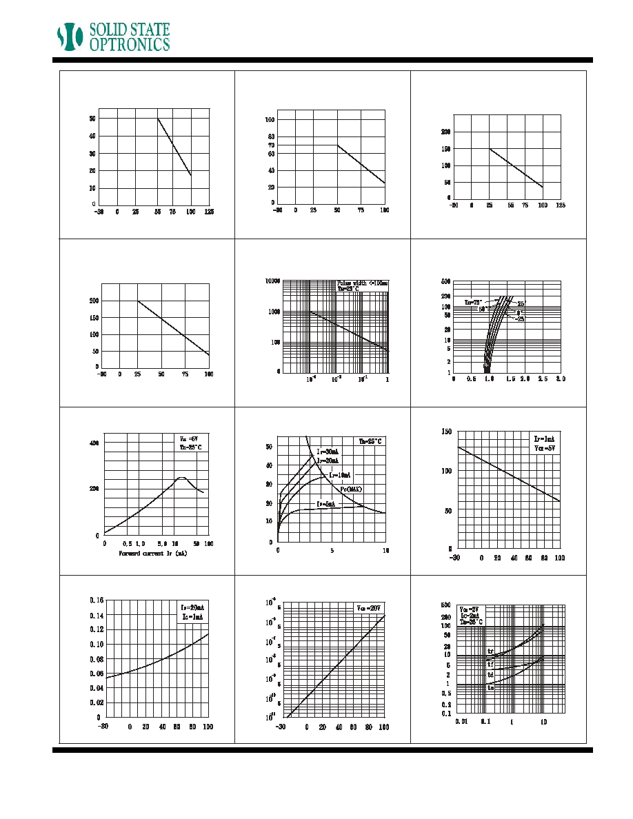
Fig.2 Diode Power Dissipation vs.
Ambient Temperature
Ambient Temperature Ta (∞C)
Diode power dissipation P (mW)
Fig.1 Forward Current vs. Ambient
Temperature
Ambient Temperature Ta (∞C)
Forward Current I
F
(mA)
Fig.3 Collector Power Dissipation vs.
Ambient Temperature
Ambient Temperature Ta (∞C)
Collector power dissipation Pc (mW)
Fig.5 Peak Forward Current vs. Duty
Ratio
Duty ratio
Peak Forward Current I
FM
(mA)
Fig.6 Forward Current vs. Forward
Voltage
Forward voltage V
F
(V)
Forward Current I
F
(mA)
Fig.8 Collector Current vs. Collector-
emitter Voltage
Collector-emitter Voltage V
CE
(V)
Collector Current Ic (mA)
Fig.9 Relative Current Transfer Ratio
vs. Ambient Temperature
Ambient Temperature Ta (∞C)
Relative current transfer ratio (%)
Fig.11 Collector Dark Current vs.
Ambient Temperature
Ambient Temperature Ta (∞C)
Collector dark current I
CEO
(A)
Fig.4 Total Power Dissipation vs.
Ambient Temperature
Ambient Temperature Ta (∞C)
T
otal power dissipation Pc (mW)
Fig.7 Current Transfer Ratio vs.
Forward Current
Forward Current I
F
(mA)
Current transfer ratio CTR (%)
Fig.10 Collector-emitter Saturation
Voltage vs. Ambient
Temperature
Ambient Temperature Ta (∞C)
Collector-emitter saturation V
oltage V
CE
(SA
T)
(V)
Fig.12 Response Time vs. Load
Resistance
Load resistance R
L
(K ohm)
Response T
ime (us)

MECHANICAL DIMENSIONS
4 PIN SMALL OUTLINE PACKAGE
rev 1.0
Solid State Optronics, Inc.
1.888.377.4776
www.ssousa.com
END VIEW
TOP VIEW
BACK VIEW
.275" ± 0.015"
(6.985 ± 0.4mm)
.80" ± 0.005"
(1.96 ± 0.13mm)
.170" ± 0.010"
(4.165 ± 0.3mm)
SAT450
AC Input
Optocoupler