
1/12
July 2005
I
HIGH SPEED: t
PD
= 9ns (MAX.) at V
CC
= 3V
I
LOW POWER DISSIPATION:
I
CC
=20
µ
A (MAX) at V
CC
=3.6V T
A
=85∞C
I
TTL COMPATIBLE INPUTS
V
IH
=2V (MIN) V
IL
=0.8(MAX)
I
OPERATING VOLTAGE RANGE:
V
CC
(OPR) = 3.0V to 3.6V
I
A PORT HAVE STANDARD 4mA TOTEM
POLE OUTPUT
I
B PORT HIGH DRIVE SOURCE/SINK
CAPABILITY OF 14mA
I
AUTO POWER-UP FEATURE TO PREVENT
PRINTER ERRORS
I
SUPPORT IEEE STD 1284-I (LEVEL 1 TYPE)
AND IEEE STD 1284-II (LEVEL 2 TYPE) FOR
BIDIRECTIONAL PARALLEL
COMMUNICATIONS BETWEEN PERSONAL
COMPUTER ANT PRINTING PERIPHERALS
I
TRANSLATION CAPABILITY ALLOW
OUTPUTS ON CABLE SIDE TO INTERFACE
WITH 5V SIGNAL
I
PULL-UP RESISTOR INTEGRATED ON ALL
OPEN-DRAIN OUTPUT ELIMINATE THE
NEED FOR DISCRETE RESISTOR
I
REPLACE THE FUNCTION OF TWO
74LVC1284 DEVICES
DESCRIPTION
The 74LVCZ161284A contains eight high speed
non inverting bidirectional buffers and eleven
control/status non-inverting buffers with open
drain outputs fabricated in silicon gate C
2
MOS
technology. It's intended to provide a standard
signaling method for a bi-direction parallel
peripheral in an Extended Capabilities Port Mode
(ECP). The HD (Active HIGH) input pin enables
the Cable port to switch from Open Drain to a high
drive totem pole output, capable of sourcing 14mA
on all thirteen buffer and 84mA on PERI LOGIC
OUTPUT buffer. The DIR input determines the
direction of data flow on the bidirectional buffers.
DIR (Active HIGH) enables data flow from A port
to B port. DIR (Active LOW) enables data flow
from B port to A port. The Y output (Y9-Y13) stay
in the high state after power-on until an associated
input A9-A13) goes high. When an associated
input goes high, all Y outputs are active, and non
74LVCZ161284A
LOW VOLTAGE HIGH SPEED IEEE1284 TRANSCEIVER
WITH ERROR-FREE POWER-UP
ORDER CODES
PACKAGE
TUBE
T & R
TSSOP
74LVCZ161284ATTR
TSSOP
PIN CONNECTION

74LVCZ161284A
2/12
inverting signals of the associated inputs are
driven through Y outputs. This special feature
prevents printer system errors caused by
deasserting the BUSY signal in the cable at
power-on.
It is available in the commercial temperature
range.
LOGIC DIAGRAM
NOTE A:
The PMOS transistors prevent backdriving current from the signal pins to V
CC/CABLE
when V
CC/CABLE
is open or at GND. The
PMOS transistor is turned off when the associated driver is in the low state.
NOTE B: The PMOS transistor prevents backdriving current from the signal pins to V
CC/CABLE
when V
CC/CABLE
is open or at GND.
NOTE C:
Active input detection circuit forces Y9-Y13 to the low state after power-on until one of the A9-A13 goes high. See below.
ACTIVE INPUT DETECTION CIRCUIT

74LVCZ161284A
3/12
PIN DESCRIPTION
TRUTH TABLE
PIN N∞
SYMBOL
NAME AND FUNCTION
1
HD
High Drive Enable Input
2, 3, 4, 5, 6
A9 to A13
Side A Input
8, 9, 11, 12, 13, 14, 16, 17
A1 to A8
Side A Input or Output
19
PLI
Peripheral Logic Input
20, 21, 22, 23
A14 to A17
Side A Output
24
HLO
Host Logic Output
25
HLI
Host Logic Input
29, 28, 27, 26
C14 to C17
Side Cable Output
30
PLO
Peripheral Logic Output
41, 40, 38, 37, 36, 35, 33, 32
B1 to B8
Side Cable Input or Output
47, 46, 45, 44, 43
Y9 to Y13
Side Cable Output
48
DIR
Direction Control Input
10, 15, 34, 39
GND
Ground (0V)
7, 18
V
CC
Positive Supply Voltage
31, 42
V
CC/CABLE
Cable Power Supply
INPUT
OUTPUT
OUTPUT
DIR
HD
L
L
B1-B8 Data to A1-A8
A9-A13 Data to Y9-Y13
C14-C17 Data to A14-A17
Y9-Y13 and PLO Open
Drain
L
H
Y9-Y13 and PLO Totem
Pole
H
L
A1-A8 Data to B1-B8
A9-A13 Data to Y9-Y13
C14-C17 Data to A14-A17
B1-B8 Y9-Y13 and PLO
Open Drain
H
H
B1-B8 Y9-Y13 and PLO
Totem Pole
74LVCZ161284A
4/12
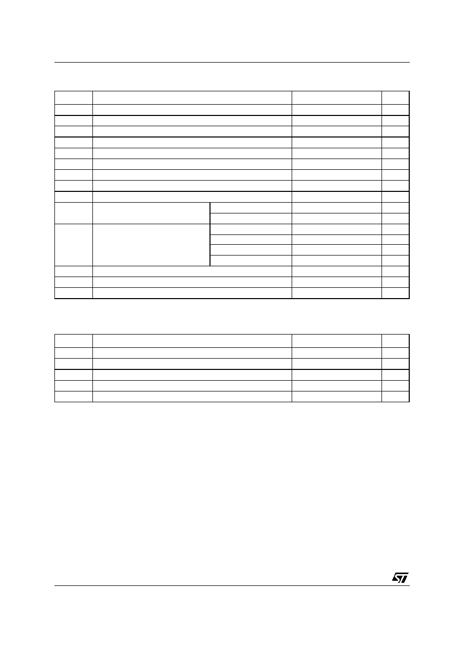
ABSOLUTE MAXIMUM RATINGS
Absolute Maximum Rating are those value beyond which damage to the device may occur. Functional operation under these condition is not
implied
RECOMMENDED OPERATING CONDITIONS
Symbol
Parameter
Value
Unit
V
CC
Supply Voltage
-0.5 to +4.6
V
V
CCcable
Cable Supply Voltage (must be
V
CC
)
-0.5 to +7.0
V
V
IA
DC Input Voltage A1-A13, PL
IN
, DIR, HD
IN
-0.5 to +V
CC
+ 0.5
V
V
IB
DC Input Voltage B1-B8, C14-C17, HL
IN
-0.5 to +5.5
V
V
IBp
DC Input Voltage B1-B8, C14-C17, HL
IN
(40ns transient)
-2 to +7
V
V
OA
DC Output Voltage A1-A8, A14-A17, HL
IN
-0.5 to +V
CC
+ 0.5
V
V
OB
DC Output Voltage B1-B8, Y9-Y13, PL
IN
-0.5 to +5.5
V
V
OBp
DC Output Voltage B1-B8, Y9-Y13, PL
IN
(40ns transient)
-2 to +7
V
I
IK
DC Input Diode Current DIR, HD A9-A13, PL
IN
C14-C17
- 20
mA
I
OK
DC Output Diode Current
A1-A8, A14-A17, HL
IN
±
50
mA
B1-B8, Y9-Y13, PL
IN
- 50
I
O
DC Output Current
A1-A8, HL
IN
±
25
mA
B1-B8, Y9-Y13
±
50
PL
O
= LOW
84
PL
O
= HIGH
-50
I
CC
or I
GND
DC V
CC
or Ground Current per Supply Pin
±
200
mA
T
stg
Storage Temperature
-65 to +150
∞C
T
L
Lead Temperature (10 sec)
300
∞C
Symbol
Parameter
Value
Unit
V
CC
Supply Voltage
3.0 to 3.6
V
V
CCcable
Cable Supply Voltage
3.0 to 5.5
V
V
I
Input Voltage
0 to V
CC
V
V
O
Open Drain Output Voltage
0 to 5.5
V
T
op
Operating Temperature
-40 to 85
∞C

74LVCZ161284A
5/12
DC SPECIFICATIONS
Symbol
Parameter
Test Condition
Value
Unit
V
CC
(V)
V
CCcable
(V)
-40 to 85 ∞C
Min.
Max.
V
IH
High Level
Input Voltage
An, Bn, PL
IN
, DIR, HD
3.0
to
3.6
3.0
to
5.5
2
V
Cn
2.3
HL
IN
2.6
V
IL
Low Level
Input Voltage
An, Bn, PL
IN
, DIR, HD
0.8
V
Cn
0.8
HL
IN
1.6
V
OH
High Level
Output Voltage
An, HL
3.0
3.0
I
O
=-50
µ
A
2.8
V
3.0
3.0
I
O
=-4mA
2.4
Bn, Yn
3.0
3.0
I
O
=-14mA
2.0
Bn, Yn
3.0
4.5
I
O
=-14mA
2.23
PL
3.15
3.15
I
O
=-500
µ
A
3.1
V
OL
Low Level
Output Voltage
An, HL
3.0
3.0
I
O
=50
µ
A
0.2
V
3.0
3.0
I
O
=4mA
0.4
Bn, Yn
3.0
3.0
I
O
=14mA
0.8
Bn, Yn
3.0
4.5
I
O
=14mA
0.77
PL
3.0
3.0
I
O
=84mA
0.95
PL
3.0
4.5
I
O
=84mA
0.90
I
I
Input Current
Cn
3.6
3.6
V
I
= V
CC
50
µ
A
3.6
3.6
V
I
=GND (Pull-up res)
-3.5
mA
All input except B or C
3.6
5.0
V
I
= V
CC
or GND
±
1
µ
A
I
CC
Quiescent Supply Current
3.6
5.0
V
I
= V
CC
I
O
=0
0.8
mA
V
I
=GND (12xPull-up)
45
I
OZ
High
Impedance
Output
Leakage
Current
Bn
3.6
5.0
V
O
= V
CC
20
µ
A
3.6
3.6
V
O
=GND (Pull-up res)
-3.5
mA
A1-A8
3.6
5.0
V
O
= V
CC
or GND
±
20
µ
A
Open Drain Y Output
3.6
3.6
V
O
=GND (Pull-up res)
-3.5
mA
I
OFF
Power Off
Leakage
Current
B, Y output (to GND)
0
5.0
V
I
or V
O
= 0 to 7V
100
µ
A
B, Y output (to V
CC
)
0
5.0
V
I
or V
O
= 0 to 7V
10
µ
A
V
hys
Input
Hysteresis
An, Bn, PL
IN
, DIR, HD
3.3
5.0
0.4
V
Cn
3.3
5.0
0.8
HL
IN
3.3
5.0
0.2
Z
O
Output
Impedance
B1-B8, Y9-Y13
3.3
5.0
V
B
= V
OH
30
55
R
P
Pull-up
Resistance
B1-B8, Y9-Y13,
C14-C17
3.3
5.0
V
B
= V
OH
1150
1650