1/10
GS-NT1+/DF3
February 2003
This is preliminary information on a new product now in development. Details are subject to change without notice.
FEATURE
s
COMBINED AC+DC CONVERTER FOR ISDN
NT1+ APPLICATION
s
Uo INTERFACE (DC) AND MAIN (AC) INPUTS
TO ENABLE NPM (Normal Power Mode) AND
RPM (Restricted Power Mode) CONDITIONS
s
INPUT FILTER TO MEET EMC
REQUIREMENTS
s
5 INSULATED MAIN OUTPUTS
s
PEAK INPUT OVERVOLTAGE
WITHSTANDING
s
INPUT FUSE ON AC MAIN INPUT
s
INPUTS TO OUTPUTS INSULATION
s
AUXILIARY LOGIC OUTPUT TTL-
COMPATIBLE FOR NPM/RPM MODE
INDICATION (EM SIGNAL & GREEN LED).
3mA OUTPUT SOURCE CURRENT
s
AUXILIARY LOGIC OUTPUT TTL-
COMPATIBLE FOR U-INTERFACE
DETECTION (RED LED. 3mA OUTPUT
SOURCE CURRENT
s
INTERNAL RELAY FUNCTION FOR V
o1
POLARITY REVERSE
s
ANALOG OUTPUTS EMERGENCY
CONDITION PROGRAMMABLE VIA
EXTERNAL COMMAND, TTL-COMPATIBLE,
1mA SINK CURRENT
s
U-INTERFACE ACCORDING TO ETR 080
WITH EXTERNAL CAPACITOR </= 2.2 uF
s
S-INTERFACE ACCORDING TO ETS 300 012
s
SAFETY COMPLIANCE ACCORDING TO
EN60950
s
MECHANICAL DIMENSIONS
(LxWxH):96x58x26.6
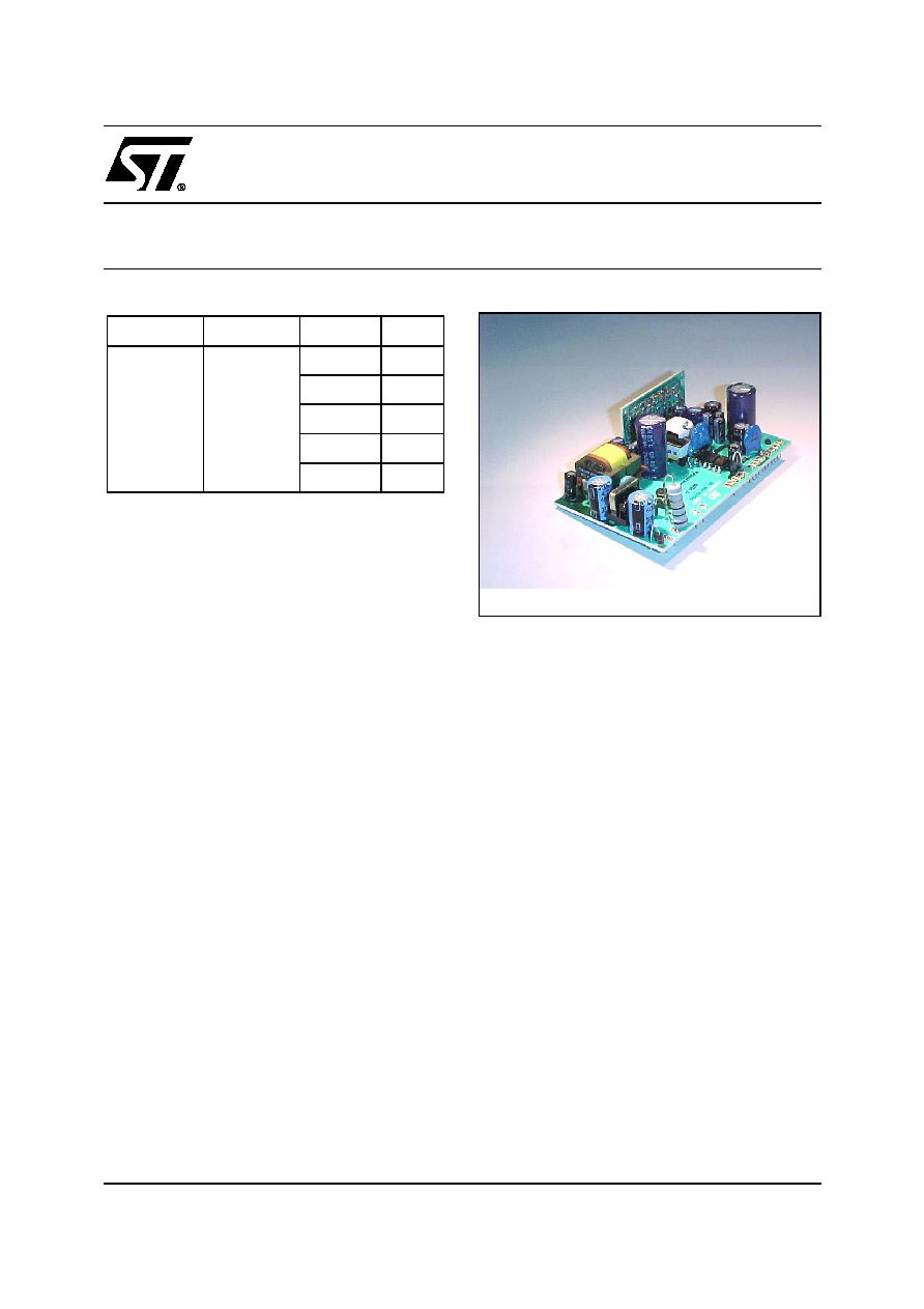
DESCRIPTION
The NT1+/DF3 Power Management Module is a
comprehensive solution for ISDN-NT1 "Plus" (Net-
work Termination Basic Access type Plus) equip-
ment, combining both AC-DC and DC-DC functions.
The NT1+/DF3 Power Management Module (NT1+
PMM) provide the NT1+ equipment with all neces-
sary supply voltages as well as control signals to op-
erate in the different operating modes, typically the
Normal Power Mode (NPM) and Restricted Power
Mode (RPM).
Connected to the main, Input 1 is the AC input power
to the NT1+ PMM, source of the whole necessary
power in normal operating mode, namely in NPM. In-
put 2 is the DC power source when in RPM, therefore
to connect to the U-INTERFACE.
When the main is available (230 V
ac
in this version)
NT1+ PMM operate in Normal Power Mode, there-
fore it supply +40V (output 1) to the S-interface being
the output power 4.5 W. Output 2 delivers 5V (up to
720 mW) for the logics and output 3 delivers -21V (up
to 900 mW). Out voltage 4 is -50V with 100 mW out-
put power. Last, output 5 delivers -135V and the out-
put power can reach peaks of 700 mW.
Type
V
i
V
o
I
o
NT1+/DF3
180<V
i1
<264
V
40<V
i2
<120
V
dc
� 40V
4.5W
� 5V
720mW
- 21V
900mW
- 50V
100mW
- 135V
700mW
ORDERING NUMBER: GS-NT1+/DF3
REV. 01
POWER MANAGEMENT MODULE FOR ISDN NT1+

GS-NT1+/DF3
2/10
When the main is missing, the module remains active but only in Restricted Power Mode (RPM). The only power
source in RPM is the Input 2, the U-Interface (V
i2
). Therefore in RPM the following condition apply to outputs 1
and 2: output 1 reverses the voltage (it becomes -40V) and the maximum power Pout is reduced to 420 mW.
P2max is reduced to 450 mW typically, however the output power available at outputs 2, 3, 4, 5 mainly depend
on input power available from the"U-Interface" V
i2
, therefore subject of variation as per local application and reg-
ulation. In RPM it is also possible to set a different "emergency condition" setting HIGH the auxiliary input 3 (an-
alog emergency input, V
in3
). In this case Pout1 is reduced to 25 mW, voltage level being -40V.
The following tables give you details of the various parameters in the 3 different operating modes, namely NPM
with V
i3
LOW, RPM with V
i3
HIGH.
Availability of the input AC main is also acknowledged by specific auxiliary output (out 6, "EM signal"), a TTL-
compatible signal set HIGH (to logic level "1") when the main is available and LOW when th AC main is missing.
The presence of the "U" is detected by an other auxiliary output (out 7) that is HIGH only when V
in2
>34 V
dc
.
The NT1+ PMM provides double insulation (3000 V
rms
) between the inputs (1 and 2), and among the input 1
and all the outputs. Basic insulation 2000 V
dc
exist among Out 1 and all the other outputs. The other outputs
(including the 2 auxiliary outputs) and the input 3, share the same common ground.
Double insulation (2000 V
rms
) is provided among Input 2 (DC "U") and all outputs.
The NT1+ Power Management Module operate in the range -10 to +70
�
C, storage temperatures in the range
-40 to +85
�
C are allowed.

3/10
GS-NT1+/DF3
ELECTRICAL CHARACTERISTICS when in NPM (T
amb
=25
)
C, unless otherwise specified.)
NPM Standard Condotion: V
in1
=180 to 264 V
rms
-------------
V
in2
=40 to 120 V
dc
Symbol
Parameter
Test Condition
Min.
Typ.
Max.
Unit
V
i1
AC Input Voltage 1
180
264
V
RMS
V
i2
DC Input Voltage 2
any polarity
40
120
V
dc
fi
V
i1
Input Frequency
V
i1
= 230 V
RMS
43
56
Hz
V
i1st
Start up Input 1 voltage
Output parameters as per NPM
Standard Condition
175
V
RMS
P
i1
Input 1 Apparent Power
NPM Standard Condition
15
VA
V
i2nd
Start up Input 2 voltage
Output parameters as per Standard
Condition
40
V
dc
V
o1
Output Voltage 1
Standard condition
34
40
42
V
V
o2
Output Voltage 2
Standard condition
4.75
5
5.25
V
V
o3
Output Voltage 3
Standard condition
-20
-21
-24
V
V
o4
Output Voltage 4
Standard condition
-48
-50
-65
V
V
o5
Output Voltage 5
Standard condition
-130
-135
-170
V
V
o6
Auxiliary Output 6(EM)
Standard condition
3.75
5
5.25
V
V
o7
Auxiliary Output 7(red LED)
Standard condition
3.75
5
5.25
V
V
or1,3,4,5
Output Ripple voltage 1,3,4,5
Standard condition BW: 0-20 MHz
100
mV
rms
V
or2
Output Ripple voltage 2
Standard condition BW: 0-20 MHz
30
mV
rms
P
o1
Output Power 1
Std. condition according to ETS300
012, E5.1.5, E5.1.6, E5.1.7 (n=4)
4.5
W
P
o2
Output Power 2
Standard condition
720
mW
P
o3
Output Power 3
Standard condition
900
mW
P
o4
Output Power 4
Standard condition
100
mW
P
o5
Output Power 5
During 1 s, 40% of the time during the
ring period at the analog interface.
The output is current limited at 2.5 mA
� 0.2 mA, with 100 uF capacitor
700
mW
V
i1th
NPM => RPM mode V
i1
threshold
Output parameters as per Standard
Condition
160
V
rms
T
tr
Transition time
transition NPM => RPM and vice
versa according to ETS300 012,
E5.1.3 (n=4)
5
ms
V
i1pk
Input 1 Transient overvoltage
t = 10/700 us as per 1TR9 Dec. 96
2000
V
V
i1pk
Input 1 Transient overvoltage
common mode test according to
ETS300 047-5p5.6
2500
V
GS-NT1+/DF3
4/10
V
i1pk
Input 1 Transient overvoltage
impuls transfer from main according
to ETS300 047-5p5.7.1
2500
V
V
o1pk
Output 1 Transient
overvoltage
t=1.2/50 us
500
V
V
is
Insulation Voltage
Input 1 to outputs and input 1 to input
2, t=60s reinforced insulation as per
EN60950
3000
V
V
ist
Insulation Voltage
Input 1 to outputs t=10/700 us (pulse)
4000
V
th
Hold-up time
V
in
= 180 V
RMS
Standard Condition
20
ms
MTBF
Mean Time Before Failure
Ground Fixed, MIL-HDBK-217E
1
Mh
Top
Oper. Ambient Temperature
-10
+70
�
C
Symbol
Parameter
Test Condition
Min.
Typ.
Max.
Unit

5/10
GS-NT1+/DF3
ELECTRICAL CHARACTERISTICS when in RPM (T
amb
=25
)
C, unless otherwise specified.)
RPM Standard Condition: V
in
1 < 100 V
rms
-------------
V
in2
= 28 to 115 V
dc
------------------
V
in3
= LOW
Symbol
Parameter
Test Condition
Min.
Typ.
Max.
Unit
V
i1
AC Input Voltage 1
100
V
rms
V
i2
DC Input Voltage 2
any polarity
40
120
V
dc
V
i2nd
Start up Input 2 voltage
Output parameters as per Std. Condition
48
V
dc
V
o1
Output Voltage 1
Standard Condition
-34
-40
-42
V
V
o2
Output Voltage 2
Standard Condition
4.75
5
5.25
V
V
o3
Output Voltage 3
Standard condition
-20
-21
-24
V
V
o4
Output Voltage 4
Standard condition
-48
-50
-65
V
V
o5
Output Voltage 5
Standard condition
-130
-135
-170
V
V
o6
Auxiliary Output 6 (EM)
Standard condition
3.75
5
5.25
V
V
o7
Auxiliary Output 7 (red LED)
Standard condition
3.75
5
5.25
V
V
or1,3,4,
5
Output Ripple Voltage 1,3,4,5
Standard condition BW :0-20 MHz
100
mV
rms
V
or2
Output Ripple Voltage 2
Standard condition BW:0-20 Mhz
30
mV
rms
P
o1
Output Power 1
Std. condition according to ETS300 012,
E5.1.1, E5.1.4.1, E5.1.4.2, E5.1.5.3 (n=4)
420
mW
P
o2
Output Power 2
Standard Condition
450
mW
P
o3
Output Power 3
Standard Condition
tbd
mW
P
o4
Output Power 4
Standard Condition
tbd
mW
P
o5
Output Power 5
Standard Condition
tbd
mW
V
i1st
RPM => NPM mode V
i1
threshold
Output parameters as per Standard
Condition
175
V
rms
T
tr
Transition TIme
transition NPM => RPM and vice versa
according to ETS300 012, E5.1.3 (n=4)
5
ms
V
i1pk
Input 1 Transient overvoltage
t = 10/700 us as per 1TR9 Dec. 96
2000
V
V
i1pk
Input 1 Transient overvoltage
common mode test according to ETS300
047-5p5.6
2500
V
V
i1pk
Input 1 Transient overvoltage
impuls transfer from main according to
ETS300 047-5p5.7.1
2500
V
V
o1pk
Output 1 Transient overvoltage t=1.2/50 us
500
V
V
is
Insulation Voltage
Input 1 to outputs and input 1 to input 2,
t=60s reinforced insulation as per
EN60950
3000
V
V
ist
Insulation Voltage
Input 1 to outputs t=10/700 us (pulse)
4000
V
th
Hold-up time
V
in
= 180 V
rms
Standard Condition
20
ms