M54/74HC160/161
M54/74HC162/163
April 1993
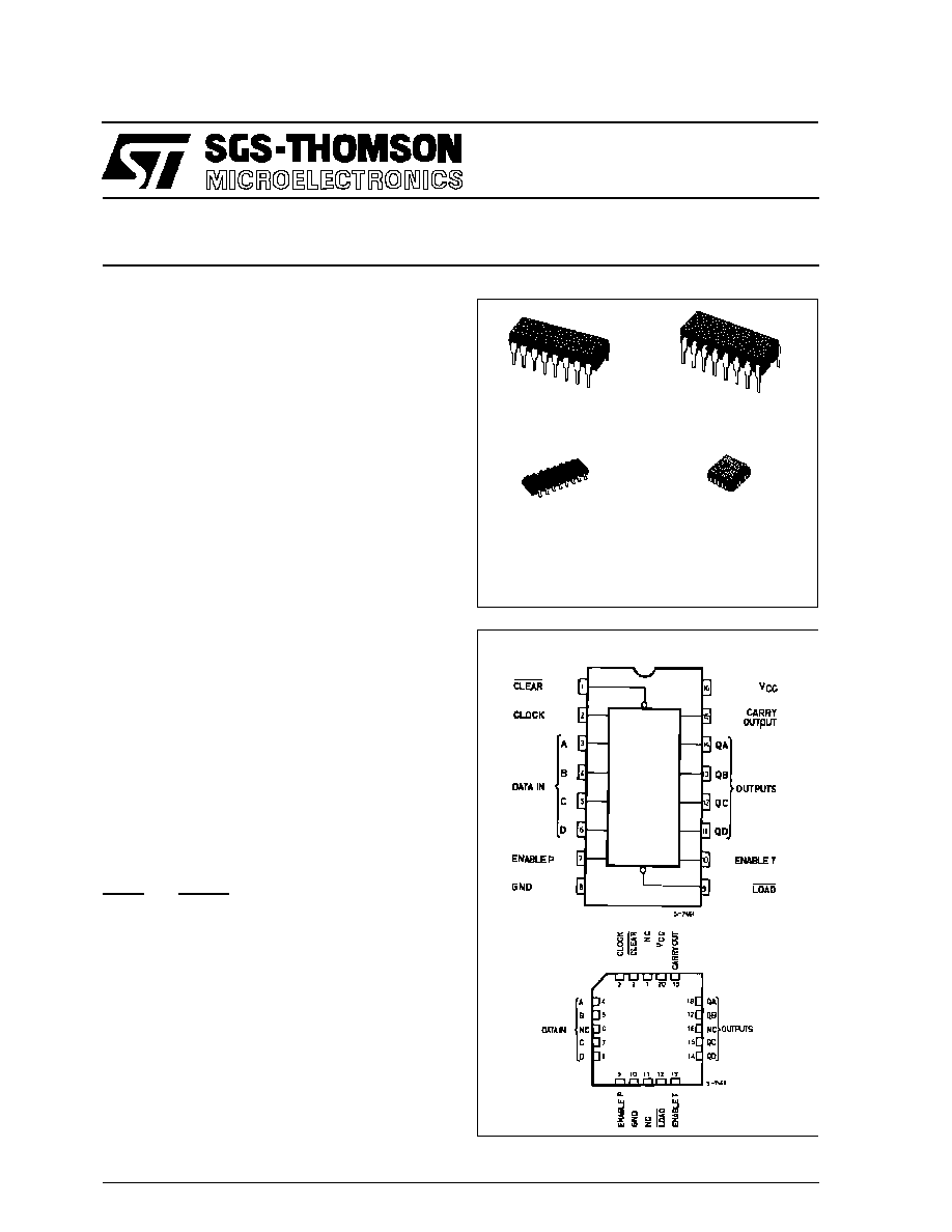
SYNCHRONOUS PRESETTABLE 4-BIT COUNTER
B1R
(Plastic Package)
ORDER CODES :
M54HCXXXF1R
M74HCXXXM1R
M74HCXXXB1R
M74HCXXXC1R
F1R
(Ceramic Package)
M1R
(Micro Package)
C1R
(Chip Carrier)
PIN CONNECTIONS (top view)
NC =
No Inter-
nal Con-
DESCRIPTION
.
HIGH SPEED
f
MAX
= 63 MHz (TYP.) AT V
CC
= 5 V
.
LOW POWER DISSIPATION
I
CC
= 4
µ
A (MAX.) AT 25
∞
C
.
OUTPUT DRIVE CAPABILITY
10 LSTTL LOADS
.
BALANCED PROPAGATION DELAYS
t
PLH
= t
PHL
.
HIGH NOISE IMMUNITY
V
NIH
= V
NIL
= 28 % V
CC
(MIN.)
.
WIDE OPERATING VOLTAGE RANGE
V
CC
(OPR) = 2 V TO 6 V
.
PIN AND FUNCTION COMPATIBLE
WITH 54/74LS160
163
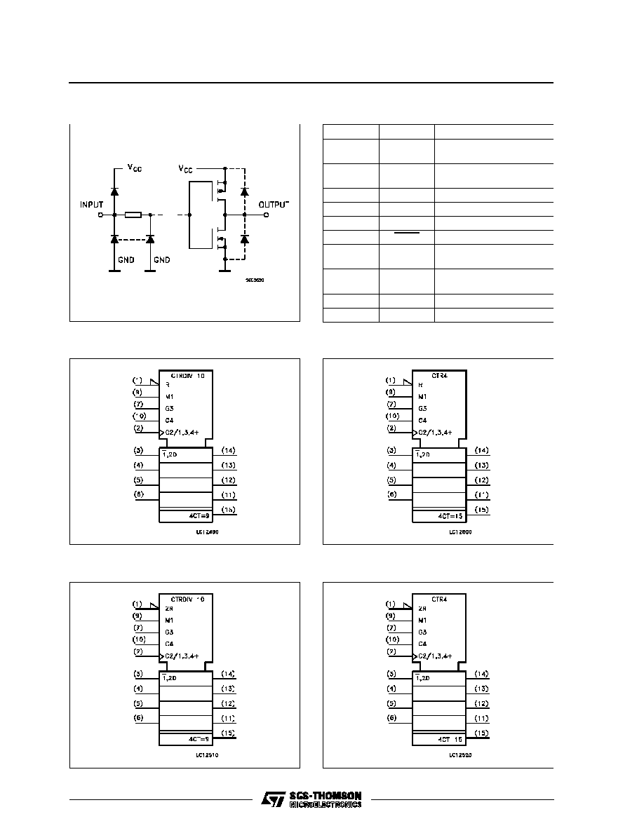
M54/74HC160 Decade, Asynchronous Clear
M54/74HC161 Binary, Asynchronous Clear
M54/74HC162 Decade, Synchronous Clear
M54/74HC163 Binary, Synchronous Clear
The M54/74HC160, 161, 162 and 163 are high
speed CMOS SYNCHRONOUS PRESETTABLE
COUNTERS fabricated with silicon gate C
2
MOS
technology.
They have the same the high speed operation simi-
lar to equivalent LSTTL while maintaining the
CMOS low power dissipation.
The M54/74HC160/162 are BCD Decade counters
and the M54/74HC161/163 are 4 bit binary counter-
s.
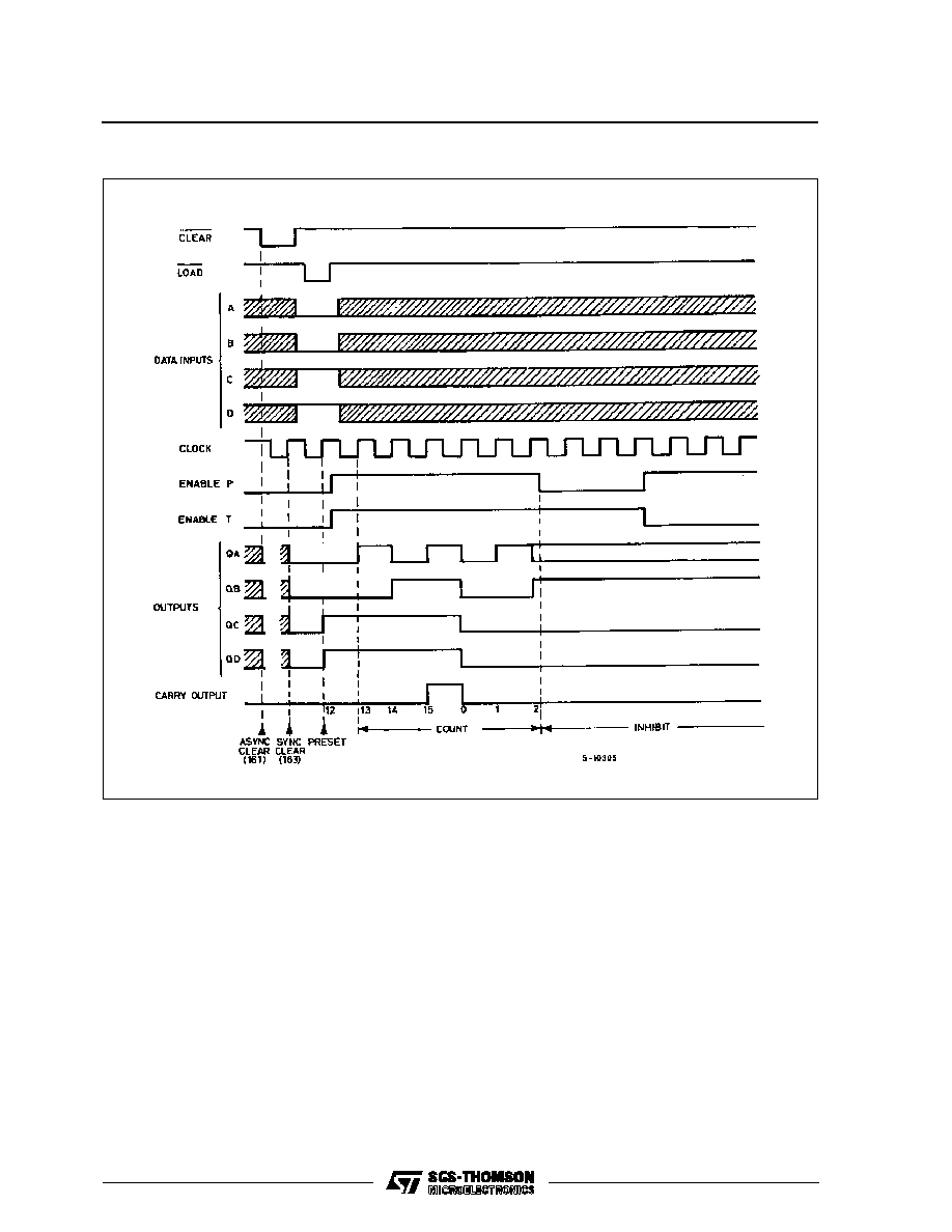
The CLOCK input is active on the rising edge. Both
LOAD and CLEAR inputs are active Low.
Presetting of all four IC's is synchronous on the ris-
ing edge of the CLOCK.
The function on the M54/74HC162/163 is syn-
chronous to CLOCK, while the M54/74HC160/161
counters are cleared asynchronously.
Two enable inputs (TE and PE) and CARRY output
are provided to enable easy cascading of counters,
which facilities easy implementation
of N-bit
counters without using external gates.
All inputs are equipped with protection circuits
against static discharge and transient excess volt-
age.
1/16
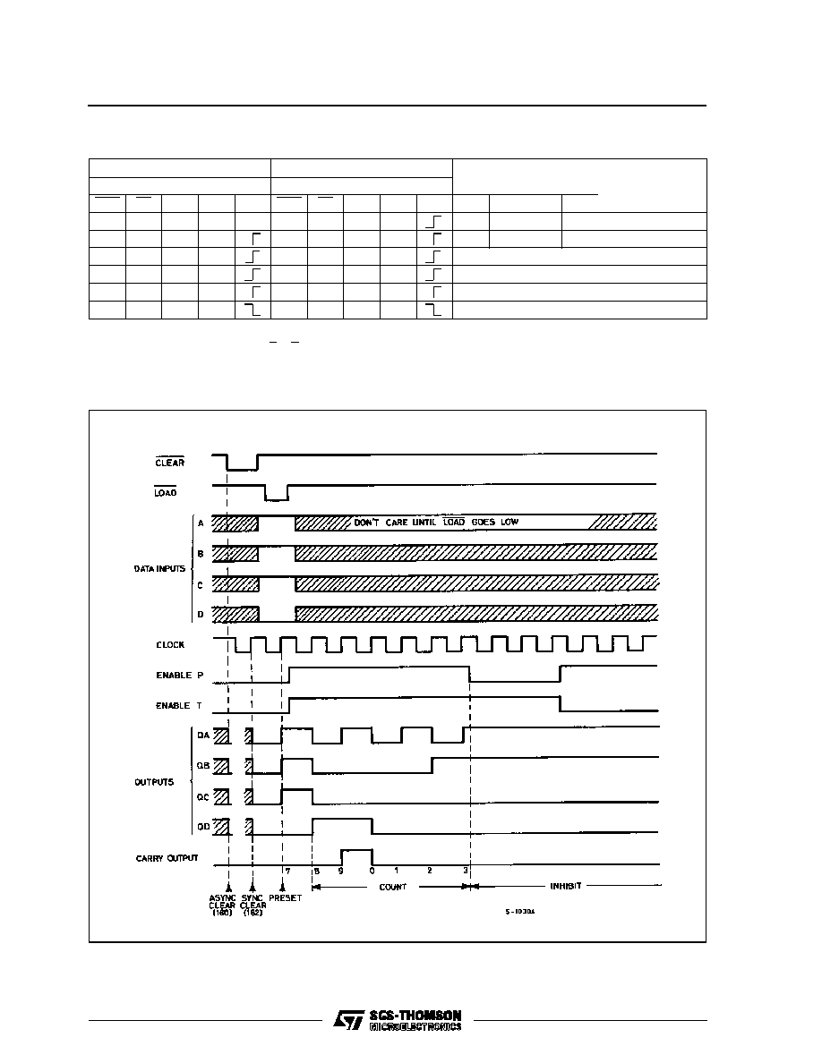
TRUTH TABLE
M54/74HC160/161
M54/74HC162/163
OUTPUTS
FUNCTION
INPUTS
INPUTS
CLR
LD
PE
TE
CK
CLR
LD
PE
TE
CK
QA
QB
QC
QD
L
X
X
X
X
L
X
X
X
L
L
L
L
RESET TO "0"
H
L
X
X
H
L
X
X
A
B
C
D
PRESET DATA
H
H
X
L
H
H
X
L
NO CHANGE
NO COUNT
H
H
L
X
H
H
L
X
NO CHANGE
NO COUNT
H
H
H
H
H
H
H
H
COUNT UP
COUNT
H
X
X
X
X
X
X
X
NO CHANGE
NO COUNT
Note:
X
: Don't Care
A, B, C, D : Logi level of data inputs
Carry
: CARRY = TE
∑
Q
A
∑
Q
B
∑
Q
C
∑
Q
D
............ (M54/74HC160/162)
: CARRY = TE
∑
Q
A
∑
Q
B
∑
Q
C
∑
Q
D
............ (M54/74HC161/163)
TIMING CHART (HC160/162 : decade counter)
M54/M74HC160/161/162/163
3/16