HF/VHF APPLICATIONS
RF & MICROWAVE TRANSISTORS
.380 4LFL (M113)
epoxy sealed
.
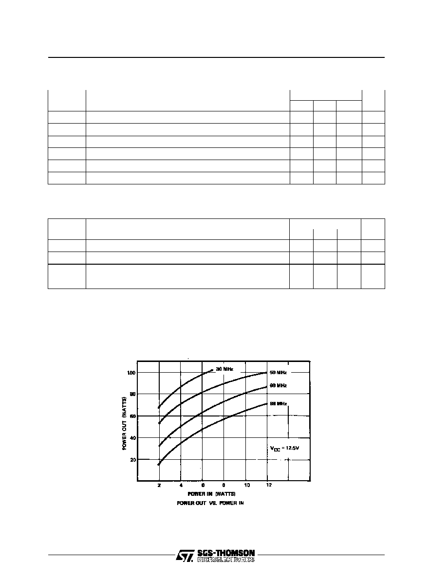
50 MHz
.
12.5 VOLTS
.
EFFICIENCY 55%
.
COMMON EMITTER
.
GOLD METALLIZATION
.
P
OUT
=
70 W MIN. WITH 10 dB GAIN
DESCRIPTION
The SD1446 is a 12.5 V Class C epitaxial silicon
NPN planar transistor designed primarily for land
mobile transmitter applications. This device utilizes
emitter ballasting and is extremely stable and ca-
pable of withstanding high VSWR under operating
conditions.
PIN CONNECTION
BRANDING
SD1446
ORDER CODE
SD1446
ABSOLUTE MAXIMUM RATINGS (T
case
=
25
∞
C)
Symbol
Parameter
Value
Uni t
V
CBO
Collector-Base Voltage
36
V
V
CEO
Collector-Emitter Voltage
18
V
V
EBO
Emitter-Base Voltage
3.5
V
I
C
Device Current
12.0
A
P
DISS
Power Dissipation
183
W
T
J
Junction Temperature
+200
∞
C
T
STG
Storage Temperature
-
65 to +150
∞
C
R
TH(j-c)
Junction-Case Thermal Resistance
1.05
∞
C/W
SD1446
1. Collector
3. Base
2. Emitter
4. Emitter
THERMAL DATA
November 1992
1/5

TEST CIRCUIT
C1, C4 : 50 - 380pF Arco 465
C2
: 110 - 580pF Arco 467
C3
: 140 - 680pF Arco 468
C5
: 9 - 180pF Arco 463
C6
: 10
µ
F, 35Vdc, Electrolytic
C7
: .01
µ
F Erie
C8
: 1000pF Unelco
L1
: 2 1/2 Turns, #14 Awg, Tinned, 1/4" I.D.
Loose Wound
L2
: 10 Turns, #28 AWG, Enameled on
Ferroxcube Sleeve #3B
L3
: 1 1/2 Turns, #12 AWG, Tinned, 3/8" I.D.
Loose Wound
L4
: 8 Turns, #18 AWG on 1/4" I.D. Coil form 1/2"
Length with Ferrite Slug
L5
: 11 Turns, #16 AWG, Enameled on Torroid,
Micrometals, T50-2
Board Material: Double Sided Copper 1/16" Thick
SD1446
4/5
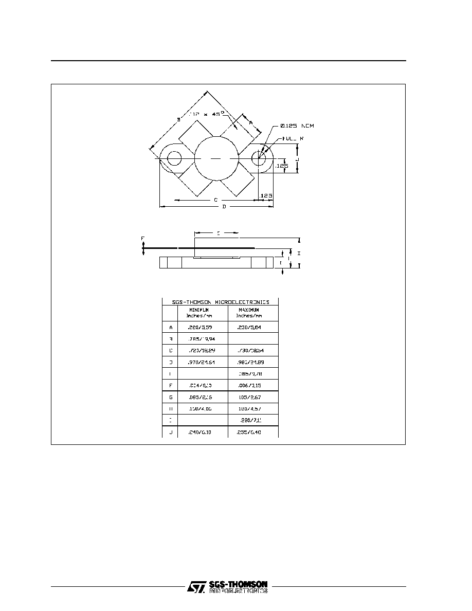
PACKAGE MECHANICAL DATA
Ref.: Dwg. No.12-0113
Information furnished is believed to be accurate and reliable. However, SGS-THOMSON Microelectronics assumes no responsability for the
consequences of use of such information nor for any infringement of patents or other rights of third parties which may results from its use. No
license is granted by implication or otherwise under any patent or patent rights of SGS-THOMSON Microelectronics. Specifications mentioned
in this publication are subject to change without notice. This publication supersedes and replaces all information previously supplied.
SGS-THOMSON Microelectronics products are not authorized for use as critical components in life support devices or systems without express
written approval of SGS-THOMSON Microelectonics.
©
1994 SGS-THOMSON Microelectronics - All Rights Reserved
SGS-THOMSON Microelectronics GROUP OF COMPANIES
Australia - Brazil - France - Germany - Hong Kong - Italy - Japan - Korea - Malaysia - Malta - Morocco - The Netherlands -
Singapore - Spain - Sweden - Switzerland - Taiwan - Thailand - United Kingdom - U.S.A
SD1446
5/5