 | –≠–ª–µ–∫—Ç—Ä–æ–Ω–Ω—ã–π –∫–æ–º–ø–æ–Ω–µ–Ω—Ç: SMP100-65 | –°–∫–∞—á–∞—Ç—å:  PDF PDF  ZIP ZIP |

SMP100-xxx
Æ
August 1999 - Ed : 8A
COMMUNICATION EQUIPMENT PROTECTION: TRISIL
TM
BIDIRECTIONAL CROWBAR PROTECTION
VOLTAGE RANGE : FROM 8V to 270V
REPETITIVE PEAK PULSE CURRENT:
I
PP
= 100 A (10/1000
µ
s)
HOLDING CURRENT: I
H
= 150mA or 225mA
LOW LEAKAGE CURRENT: I
R
= 2
µ
A max
FEATURES
The SMP100 series are transient surge ar-
restors used for the protection of sensitive tele-
com equipment.
DESCRIPTION
SCHEMATIC DIAGRAM
Any sensitive equipment requiring protection
against lightning strikes :
ANALOG AND DIGITAL LINE CARDS
MAIN DISTRIBUTION FRAMES
TERMINALS AND TRANSMISSION
EQUIPMENT
GAS-TUBE REPLACEMENT
MAIN APPLICATIONS
NO AGEING AND NO NOISE
IF DESTROYED, THE SMP100 FALLS INTO
SHORT CIRCUIT,STILLENSURINGPROTECTION
BOARD SPACE SAVING
BENEFITS
SMB
(JEDEC DO-214AA)
COMPLIES WITH THE
FOLLOWING STANDARDS:
Peak Surge
Voltage
(V)
Voltage
Waveform
(
µ
s)
Current
Waveform
(
µ
s)
Admissible
Ipp
(A)
Necessary
Resistor
(
)
ITU K20
4000
10/700
5/310
100
-
VDE0433
4000
10/700
5/310
100
-
VDE0878
4000
1.2/50
1/20
100
-
IEC-1000-4-5
level 4
level 4
10/700
1.2/50
5/310
8/20
100
100
-
-
FCC Part 68, lightning surge
type A
1500
800
10/160
10/560
10/160
10/560
200
100
-
-
FCC Part 68, lightning surge
type B
100
9/720
5/320
25
-
BELLCORE TR-NWT-001089
First level
2500
1000
2/10
10/1000
2/10
10/1000
500
100
-
-
BELLCORE TR-NWT-001089
Second level
5000
2/10
2/10
500
-
CNET l31-24
4000
0.5/700
0.8/310
100
-
1/9

Symbol
Parameter
Value
Unit
R
th(j-I)
Junction to leads
20
∞
C/W
R
th(j-a)
Junction to ambient on printed circuit
(with standard footprint dimensions)
100
∞
C/W
THERMAL RESISTANCES
Symbol
Parameter
Value
Unit
I
pp
Peak pulse current:
10/1000
µ
s (open circuit voltage waveform 1 kV
10/1000
µ
s)
5/310
µ
s
(open circuit voltage waveform 4 kV, 10/700
µ
s)
8/20
µ
s
(open circuit voltage waveform 4 kV
1.2/50
µ
s)
2/10
µ
s
(open circuit voltage waveform 2.5kV
2/10
µ
s)
100
150
250
500
A
A
A
A
I
FS
Fail-safe mode
8/20
µ
s
5
kA
I
TSM
Non repetitive surge peak on-state current
One cycle
50Hz
60Hz
55
60
A
A
Non repetitive surge peak on-state current
F = 50Hz
0.2s
2s
25
12
A
A
T
L
Maximum lead temperature for soldering during 10s
260
∞
C
T
stg
Tj
Storage temperature range
Maximum junction temperature
- 55 to + 150
150
∞
C
∞
C
ABSOLUTE MAXIMUM RATINGS (T
amb
=
25
∞
C)
100
50
% IPP
t
t
r
p
0
t
Note 1: Pulse waveform
10 / 1000
µ
s
tr = 10
µ
s
tp = 1000
µ
s
8 / 20
µ
s
tr = 8
µ
s
tp = 20
µ
s
5 / 310
µ
s
tr = 5
µ
s
tp = 310
µ
s
1 / 20
µ
s
tr = 1
µ
s
tp = 20
µ
s
2 / 10
µ
s
tr = 2
µ
s
tp = 10
µ
s
SMP100-xxx
2/9

Type
I
RM
@ V
RM
max.
I
R
@ V
R
max.
note 1
V
BO
@ I
BO
max.
note 2
I
H
min.
note 3
C
typ.
note 4
µ
A
V
µ
A
V
V
mA
mA
pF
SMP100-8
2
6
50
8
20
800
50(typ)
100
SMP100LC-35
2
32
50
35
55
800
150
90
SMP100-65
2
55
50
65
80
800
150
160
SMP100-120
2
110
50
120
160
800
150
140
SMP100-140
2
120
50
140
200
800
150
140
SMP100-200
2
170
50
200
265
800
150
130
SMP100-230
2
200
50
230
300
800
150
120
SMP100-270
2
230
50
270
350
800
150
120
SMP100-140H225
2
120
50
140
200
800
225
140
SMP100-200H225
2
170
50
200
265
800
225
130
SMP100-230H225
2
200
50
230
300
800
225
130
SMP100-270H225
2
230
50
270
350
800
225
120
Note 1 : IR measured at VR guarantees VBR>VR
Note 2 : Measured at 50Hz, see test circuit 1. In any case VBOmin
VBR
Note 3 : See functional holding current test circuit 2.
Note 4 : VR=1V bias, VRMS=1V, F=1MHz.
STATIC PARAMETERS
Symbol
Parameter
V
RM
Stand-off voltage
I
RM
Leakage current at stand-off voltage
V
R
Continuous reverse voltage
I
R
Continuous reverse current
V
BR
Breakdown voltage
V
BO
Breakover voltage
I
H
Holding current
I
BO
Breakover current
I
PP
Peak pulse current
C
Capacitance
ELECTRICAL CHARACTERISTICS (T
amb
= 25
∞
C)
SMP100-xxx
3/9
Symbol
Test conditions (see note 5)
Type
Max.
Unit
V
BO
Test conditions 1
dV/dt = 100 V/
µ
s, di/dt < 10 A/
µ
s, I
PP
= 100 A
Test conditions 2
dV/dt = 1 kV/
µ
s, di/dt < 10 A/
µ
s, I
PP
= 10 A
SMP100-8
25
V
SMP100LC-35
55
SMP100-65
95
SMP100-120
200
SMP100-140
220
SMP100-200
285
SMP100-230
320
SMP100-270
370
SMP100-140H225
220
SMP100-200H225
285
SMP100-230H225
320
SMP100-270H225
370
Note 5 : VBO parameters are given by a KeyTek 'System 2' generator with PN246I module.
See test circuits 3 for VBO dynamic parameters.
DYNAMIC PARAMETERS
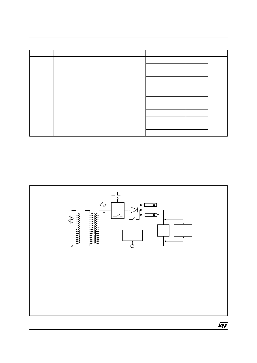
TEST CIRCUIT 1 FOR I
BO
and V
BO
parameters:
TEST PROCEDURE :
Pulse Test duration (tp = 20ms):
- For Bidirectional devices = Switch K is closed
- For Unidirectional devices = Switch K is open.
V
OUT
Selection
- Device with V
BO
<
200 Volt
- V
OUT
= 250 V
RMS
, R
1
= 140
.
- Device with V
BO
200 Volt
- V
OUT
= 480 V
RMS
, R
2
= 240
.
220V
static
relay.
R1
R2
240
140
D.U.T
V BO
measure
IBO
measure
tp = 20ms
K
Transformer
220V/800V
5A
Auto
Transformer
220V/2A
Vout
SMP100-xxx
4/9

TEST CIRCUIT 2 for I
H
parameter.
R
- V
P
V
BAT
= - 48 V
Surge generator
D.U.T.
This is a GO-NO GO test which allows to confirm the holding current (I
H
) level in a functional test circuit.
TEST PROCEDURE :
- Adjust the current level at the I
H
value by short circuiting the D.U.T.
- Fire the D.U.T. with a surge current : I
pp
= 10A, 10/1000
µ
s.
- The D.U.T. will come back to the off-state within 50 ms max.
100 V /
µ
s, di/dt < 10 A /
µ
s, Ipp = 100 A
1 kV /
µ
s, di/dt < 10 A /
µ
s, Ipp = 10 A
U
U
10
µ
F
2
45
66
470
83
0.36 nF
46
µ
H
60
µ
F
26
µ
H
12
250
46
µ
H
47
KeyTek 'System 2' generator with PN246I module
KeyTek 'System 2' generator with PN246I module
TEST CIRCUITS 3 FOR V
BO
DYNAMIC PARAMETERS
SMP100-xxx
5/9