
1/21
PRELIMINARY DATA
December 2004
This is preliminary information on a new product now in development or undergoing evaluation. Details are subject to change without notice.
STM6321/6322
STM6821/6822/6823/6824/6825
5-Pin Supervisor with
Watchdog Timer and Push-button Reset
FEATURES SUMMARY
PRECISION V
CC
MONITORING OF 5V, 3.3V,
3V, OR 2.5V POWER SUPPLIES
≠
STM6xxxL
≠
STM6xxxM
≠
STM6xxxT
≠
STM6xxxS
≠
STM6xxxR
≠
STM6xxxZ
RST OUTPUTS (ACTIVE-LOW, PUSH-PULL
OR OPEN DRAIN)
RST OUTPUTS (ACTIVE-HIGH, PUSH-
PULL)
200ms (TYP) t
rec
WATCHDOG TIMER - 1.6sec (TYP)
MANUAL RESET INPUT (MR)
LOW SUPPLY CURRENT - 3µA (TYP)
GUARANTEED RST (RST) ASSERTION
DOWN TO V
CC
= 1.0V
OPERATING TEMPERATURE:
≠40∞C to 85∞C (Industrial Grade)
Figure 1. Package
Table 1. Device Options
SOT23-5 (WY)
Part Number
Watchdog Input
Manual Reset
Input
Reset Output
Active-Low
(Push-pull)
Active-High
(Push-pull)
Active-Low
(Open Drain)
STM6321
STM6322
STM6821
STM6822
STM6823
STM6824
STM6825

STM6321/6322/6821/6822/6823/6824/6825
2/21
TABLE OF CONTENTS
FEATURES SUMMARY . . . . . . . . . . . . . . . . . . . . . . . . . . . . . . . . . . . . . . . . . . . . . . . . . . . . . . . . . . . . . 1
Figure 1. Package. . . . . . . . . . . . . . . . . . . . . . . . . . . . . . . . . . . . . . . . . . . . . . . . . . . . . . . . . . . . . . . 1
Table 1. Device Options . . . . . . . . . . . . . . . . . . . . . . . . . . . . . . . . . . . . . . . . . . . . . . . . . . . . . . . . . 1
SUMMARY DESCRIPTION . . . . . . . . . . . . . . . . . . . . . . . . . . . . . . . . . . . . . . . . . . . . . . . . . . . . . . . . . . . 4
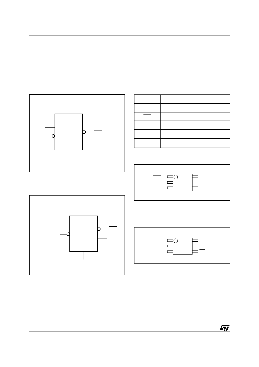
Figure 2. Logic Diagram (STM6821/6822/6823). . . . . . . . . . . . . . . . . . . . . . . . . . . . . . . . . . . . . . . . 4
Figure 3. Logic Diagram (STM6321/6322/6824/6825) . . . . . . . . . . . . . . . . . . . . . . . . . . . . . . . . . . . 4
Table 2. Signal Names . . . . . . . . . . . . . . . . . . . . . . . . . . . . . . . . . . . . . . . . . . . . . . . . . . . . . . . . . . 4
Figure 4. STM6821/6822/6823 SOT23-5 Connections. . . . . . . . . . . . . . . . . . . . . . . . . . . . . . . . . . . 4
Figure 5. STM6321/6322/6824/6825 SOT23-5 Connections . . . . . . . . . . . . . . . . . . . . . . . . . . . . . . 4
Pin Descriptions . . . . . . . . . . . . . . . . . . . . . . . . . . . . . . . . . . . . . . . . . . . . . . . . . . . . . . . . . . . . . . . 5
Active-Low, Push-pull Reset Output (RST) - STM6822/6823/6824/6825 . . . . . . . . . . . . . . . . . . . . . 5
Active-Low, Open Drain Reset Output (RST) - STM6321/6322/6822 . . . . . . . . . . . . . . . . . . . . . . . . 5
Push-button Reset Input (MR) . . . . . . . . . . . . . . . . . . . . . . . . . . . . . . . . . . . . . . . . . . . . . . . . . . . . . . 5
Watchdog Input (WDI) . . . . . . . . . . . . . . . . . . . . . . . . . . . . . . . . . . . . . . . . . . . . . . . . . . . . . . . . . . . . 5
Active-High Reset Output . . . . . . . . . . . . . . . . . . . . . . . . . . . . . . . . . . . . . . . . . . . . . . . . . . . . . . . . . 5
Table 3. Pin Functions . . . . . . . . . . . . . . . . . . . . . . . . . . . . . . . . . . . . . . . . . . . . . . . . . . . . . . . . . . . 5
Figure 6. Block Diagram (STM6xxx) . . . . . . . . . . . . . . . . . . . . . . . . . . . . . . . . . . . . . . . . . . . . . . . . . 5
Figure 7. Hardware Hookup . . . . . . . . . . . . . . . . . . . . . . . . . . . . . . . . . . . . . . . . . . . . . . . . . . . . . . . 6
OPERATION . . . . . . . . . . . . . . . . . . . . . . . . . . . . . . . . . . . . . . . . . . . . . . . . . . . . . . . . . . . . . . . . . . . . . . 7
Reset Output . . . . . . . . . . . . . . . . . . . . . . . . . . . . . . . . . . . . . . . . . . . . . . . . . . . . . . . . . . . . . . . . . . 7
Open Drain RST Output . . . . . . . . . . . . . . . . . . . . . . . . . . . . . . . . . . . . . . . . . . . . . . . . . . . . . . . . . 7
Figure 8. STM6321/6322/6822 Open Drain RST Output with Multiple Supplies . . . . . . . . . . . . . . . 7
Push-button Reset Input (STM6322/6821/6822/6823/6825) . . . . . . . . . . . . . . . . . . . . . . . . . . . . . 7
Watchdog Input (STM6321/6821/6822/6823/6824) . . . . . . . . . . . . . . . . . . . . . . . . . . . . . . . . . . . . 7
Applications Information . . . . . . . . . . . . . . . . . . . . . . . . . . . . . . . . . . . . . . . . . . . . . . . . . . . . . . . . 7
Watchdog Input Current . . . . . . . . . . . . . . . . . . . . . . . . . . . . . . . . . . . . . . . . . . . . . . . . . . . . . . . . . . 7
Ensuring a Valid Reset Output Down to V
CC
= 0V . . . . . . . . . . . . . . . . . . . . . . . . . . . . . . . . . . . . . . 8
Interfacing to Microprocessors with Bi-directional Reset Pins . . . . . . . . . . . . . . . . . . . . . . . . . 8
Figure 9. Ensuring RST Valid to V
CC
= 0, (Active-Low Push-pull Outputs) . . . . . . . . . . . . . . . . . . . 8
Figure 10.Ensuring RST Valid to V
CC
= 0, (Active-High, Push-pull Outputs) . . . . . . . . . . . . . . . . . . 8
Figure 11.Interfacing to Microprocessors with Bi-directional Reset I/O . . . . . . . . . . . . . . . . . . . . . . . 8
TYPICAL OPERATING CHARACTERISTICS . . . . . . . . . . . . . . . . . . . . . . . . . . . . . . . . . . . . . . . . . . . . 9
Figure 12.V
CC
-to-Reset Output Delay vs. Temperature . . . . . . . . . . . . . . . . . . . . . . . . . . . . . . . . . . 9
Figure 13.Supply Current vs. Temperature . . . . . . . . . . . . . . . . . . . . . . . . . . . . . . . . . . . . . . . . . . . . 9
Figure 14.MR-to-Reset Output Delay vs. Temperature . . . . . . . . . . . . . . . . . . . . . . . . . . . . . . . . . . 10
Figure 15.Normalized Power-up t
rec
vs. Temperature. . . . . . . . . . . . . . . . . . . . . . . . . . . . . . . . . . . 10
Figure 16.Normalized Reset Threshold Voltage vs. Temperature . . . . . . . . . . . . . . . . . . . . . . . . . 11
Figure 17.Normalized Power-up Watchdog Time-Out Period . . . . . . . . . . . . . . . . . . . . . . . . . . . . . 11
Figure 18.Voltage Output Low vs. I
SINK. . . . . . . . . . . . . . . . . . . . . . . . . . . . . . . . . . . . . . . . . . . . . . . . . . . . . . . . . . 12
Figure 19.Voltage Output High vs. I
SOURCE. . . . . . . . . . . . . . . . . . . . . . . . . . . . . . . . . . . . . . . . . . . . . . . . . . . . . . 12

3/21
STM6321/6322/6821/6822/6823/6824/6825
Figure 20.Maximum Transient Duration vs. Reset Threshold Overdrive. . . . . . . . . . . . . . . . . . . . . 13
MAXIMUM RATING. . . . . . . . . . . . . . . . . . . . . . . . . . . . . . . . . . . . . . . . . . . . . . . . . . . . . . . . . . . . . . . . 14
Table 4. Absolute Maximum Ratings . . . . . . . . . . . . . . . . . . . . . . . . . . . . . . . . . . . . . . . . . . . . . . . 14
DC AND AC PARAMETERS. . . . . . . . . . . . . . . . . . . . . . . . . . . . . . . . . . . . . . . . . . . . . . . . . . . . . . . . . 15
Table 5. Operating and AC Measurement Conditions . . . . . . . . . . . . . . . . . . . . . . . . . . . . . . . . . . 15
Figure 21.AC Testing Input/Output Waveforms. . . . . . . . . . . . . . . . . . . . . . . . . . . . . . . . . . . . . . . . 15
Figure 22.MR Timing Waveform . . . . . . . . . . . . . . . . . . . . . . . . . . . . . . . . . . . . . . . . . . . . . . . . . . . 15
Figure 23.Watchdog Timing . . . . . . . . . . . . . . . . . . . . . . . . . . . . . . . . . . . . . . . . . . . . . . . . . . . . . . 15
Table 6. DC and AC Characteristics . . . . . . . . . . . . . . . . . . . . . . . . . . . . . . . . . . . . . . . . . . . . . . . 16
PACKAGE MECHANICAL . . . . . . . . . . . . . . . . . . . . . . . . . . . . . . . . . . . . . . . . . . . . . . . . . . . . . . . . . . 18
Figure 24.SOT23-5 ≠ 5-lead Small Outline Transistor Package Mechanical Drawing . . . . . . . . . . 18
Table 7. SOT23-5 ≠ 5-lead Small Outline Transistor Package Mechanical Data . . . . . . . . . . . . . 18
PART NUMBERING . . . . . . . . . . . . . . . . . . . . . . . . . . . . . . . . . . . . . . . . . . . . . . . . . . . . . . . . . . . . . . . 19
Table 8. Ordering Information Scheme . . . . . . . . . . . . . . . . . . . . . . . . . . . . . . . . . . . . . . . . . . . . . 19
Table 9. Marking Description . . . . . . . . . . . . . . . . . . . . . . . . . . . . . . . . . . . . . . . . . . . . . . . . . . . . . 19
REVISION HISTORY. . . . . . . . . . . . . . . . . . . . . . . . . . . . . . . . . . . . . . . . . . . . . . . . . . . . . . . . . . . . . . . 20
Table 10. Document Revision History . . . . . . . . . . . . . . . . . . . . . . . . . . . . . . . . . . . . . . . . . . . . . . . 20
STM6321/6322/6821/6822/6823/6824/6825
4/21
SUMMARY DESCRIPTION
The STM6xxx Supervisors are self-contained de-
vices which provide microprocessor supervisory
functions. A precision voltage reference and com-
parator monitors the V
CC
input for an out-of-toler-
ance condition. When an invalid V
CC
condition
occurs, the reset output (RST) is forced low (or
high in the case of RST). These devices also offer
a watchdog timer (except for STM6322/6825) and/
or a push-button (MR) reset input.
These devices are available in a standard 5-pin
SOT23 package.
Figure 2. Logic Diagram (STM6821/6822/6823)
Note: 1. For STM6821 only.
Figure 3. Logic Diagram (STM6321/6322/6824/
6825)
Note: 1. For STM6321/6824
Table 2. Signal Names
Figure 4. STM6821/6822/6823 SOT23-5
Connections
Note: 1. Push-pull only.
2. Open Drain for STM6822.
Figure 5. STM6321/6322/6824/6825 SOT23-5
Connections
Note: 1. Open Drain for STM6321/6322.
2. Push-pull only.
3. For STM6321/6824
AI09128
V
CC
STM6XXX
V
SS
RST (RST)
(1)
WDI
MR
AI09129
V
CC
STM6XXX
V
SS
RST
RST
(WDI)
(1)
MR
MR
Push-button Reset Input
WDI
Watchdog Input
RST
Active-Low Reset Output
RST
Active-High Reset Output
V
CC
Supply Voltage
V
SS
Ground
1
WDI
RST
(1)
(RST)
(2)
V
CC
MR
V
SS
AI09130
SOT23-5
2
3
4
5
1
V
CC
V
SS
AI09131
SOT23-5
2
3
4
5
MR (WDI)
(3)
RST
(1)
RST
(2)

5/21
STM6321/6322/6821/6822/6823/6824/6825
Pin Descriptions
Active-Low, Push-pull Reset Output (RST) -
STM6822/6823/6824/6825. Pulses low when trig-
gered, and stays low whenever V
CC
is below the
reset threshold or when MR is a logic low. It re-
mains low for t
rec
after either V
CC
rises above the
reset threshold, the watchdog triggers a reset, or
MR goes from low to high.
Active-Low, Open Drain Reset Output (RST) -
STM6321/6322/6822. Pulses low when triggered,
and stays low whenever V
CC
is below the reset
threshold or when MR is a logic low. It remains low
for t
rec
after either V
CC
rises above the reset
threshold, the watchdog triggers a reset, or MR
goes from low to high. Connect a pull-up resistor
to supply voltage.
Push-button Reset Input (MR). A logic low on
MR asserts the reset output. Reset remains as-
serted as long as MR is low and for t
rec
after MR
returns high. This active-low input has an internal
52k
pull-up. It can be driven from a TTL or CMOS
logic line, or shorted to ground with a switch.
Leave open if unused.
Watchdog Input (WDI). If WDI remains high or
low for at least 1.6sec, the internal watchdog timer
expires and reset is asserted. The internal watch-
dog timer clears while reset is asserted or when
WDI sees a rising or falling edge. The watchdog
function CAN be disabled if WDI is left unconnect-
ed or is connected to a tri-state buffer output.
Active-High Reset Output. Active-high, push-
pull reset output; inverse of RST.
Table 3. Pin Functions
Figure 6. Block Diagram (STM6xxx)
Note: 1. For STM6321/6821/6822/6823/6824
2. For STM6322/6821/6822/6823/6825
3. For STM6821/ (RST output only)
4. For STM6321/6322/6824/6825 (both RST and RST outputs)
Pin
Name
Function
STM6822
STM6823
STM6821
STM6321
STM6824
STM6322
STM6825
1
≠
1
1
RST
Active-Low Reset Output
3
3
≠
4
MR
Push-button Reset Input
4
4
4
≠
WDI
Watchdog Input
≠
1
3
3
RST
Active-High Reset Output
5
5
5
5
V
CC
Supply Voltage
2
2
2
2
V
SS
Ground
AI09132
V
RST
RST (RST)
(3)
WATCHDOG
TIMER
WDI
Transitional
Detector
COMPARE
t
rec
Generator
V
CC
WDI
(1)
MR
(2)
RST
(4)
V
CC