
STPR1620CG
STPR1620CT
Æ
July 1999- Ed:2B
ULTRA-FAST RECOVERY RECTIFIER DIODES
D
2
PAK
STPR1620CG
SUITED FOR SMPS
LOW LOSSES
LOW FORWARD AND REVERSE RECOVERY
TIME
HIGH SURGE CURRENT CAPABILITY
FEATURES
Low cost dual center tap rectifier suited for
Switched
Mode
Power
Supplies and
high
frequency DC to DC converters.
Packaged in D
2
PAK or TO-220AB, this device is
intended for use in low voltage, high frequency
inverters, free wheeling and polarity protection
applications.
DESCRIPTION
Symbol
Parameter
Value
Unit
V
RRM
Repetitive peak reverse voltage
200
V
I
F(RMS)
RMS forward current
20
A
I
F(AV)
Average forward current
= 0.5
Tc=120
∞
C Per diode
Per device
8
16
A
I
FSM
Surge non repetitive forward current
tp=10ms sinusoidal
80
A
T
stg
Storage temperature range
- 65 to + 150
∞
C
Tj
Maximum operating junction temperature
150
∞
C
ABSOLUTE RATINGS (limiting values, per diode)
K
K
A2
A1
A1
K
A2
I
F(AV)
2 x 8 A
V
RRM
200 V
Tj (max)
150
∞
C
V
F
(max)
0.99 V
trr (max)
30 ns
MAIN PRODUCTS CHARACTERISTICS
TO-220AB
STPR1620CT
K
A1
A2
1/6

Symbol
Test conditions
Min.
Typ.
Max.
Unit
I
R
*
T
j
= 25
∞
C
V
R
= V
RRM
50
µ
A
T
j
= 100
∞
C
0.2
0.6
mA
V
F **
T
j
= 125
∞
C
I
F
= 8 A
0.8
0.99
V
T
j
= 125
∞
C
I
F
= 16 A
0.95
1.20
T
j
= 25
∞
C
I
F
= 16 A
1.25
Pulse test : * tp = 5 ms,
< 2 %
** tp = 380
µ
s,
< 2 %
To evaluate the conduction losses use the following equation :
P = 0.78 x I
F(AV)
+ 0.026 x I
F
2
(RMS)
STATIC ELECTRICAL CHARACTERISTICS
Symbol
Test conditions
Min.
Typ.
Max.
Unit
trr
T
j
= 25
∞
C
I
F
= 0.5A
I
R
= 1A
Irr = 0.25A
30
ns
tfr
T
j
= 25
∞
C
I
F
= 3A
V
FR
= 1.1 x V
F
max
dI
F
/dt = 50 A/
µ
s
20
ns
V
FP
T
j
= 25
∞
C
I
F
= 3A
dI
F
/dt = 50 A/
µ
s
3
V
RECOVERY CHARACTERISTICS
Symbol
Parameter
Value
Unit
R
th (j-c)
Junction to case
Per diode
3.0
∞
C/W
Total
1.8
∞
C/W
R
th (c)
Coupling
0.6
∞
C/W
When the diodes 1 and 2 are used simultaneously :
Tj(diode 1) = P(diode 1) x Rth(j-c) (Per diode) + P(diode 2) x Rth(c)
THERMAL RESISTANCES
STPR1620CG / STPS1620CT
2/6

Fig. 2: Peak current versus form factor (per diode).
Fig. 3: Average current versus ambient
temperature (
: 0.5, per diode).
Fig. 4: Non repetitive surge peak forward current
versus overload duration (maximum values, per
diode).
Fig. 1: Average forward power dissipation versus
average forward current (per diode).
Fig. 5: Relative variation of thermal transient
impedance junction to case versus pulse duration
(per diode).
Fig. 6: Forward voltage drop versus forward
current (maximum values, per diode).
STPR1620CG / STRP1620CT
3/6

H
Fig. 7: Junction capacitance versus reverse
voltage applied (typical values, per diode).
Fig. 8: Recovery charges versus dI
F
/dt (per diode).
Fig. 10: Dynamic parameters versus junction
temperature (per diode).
Fig. 9: Peak reverse current versus dI
F
/dt (per
diode).
STPR1620CG / STPS1620CT
4/6
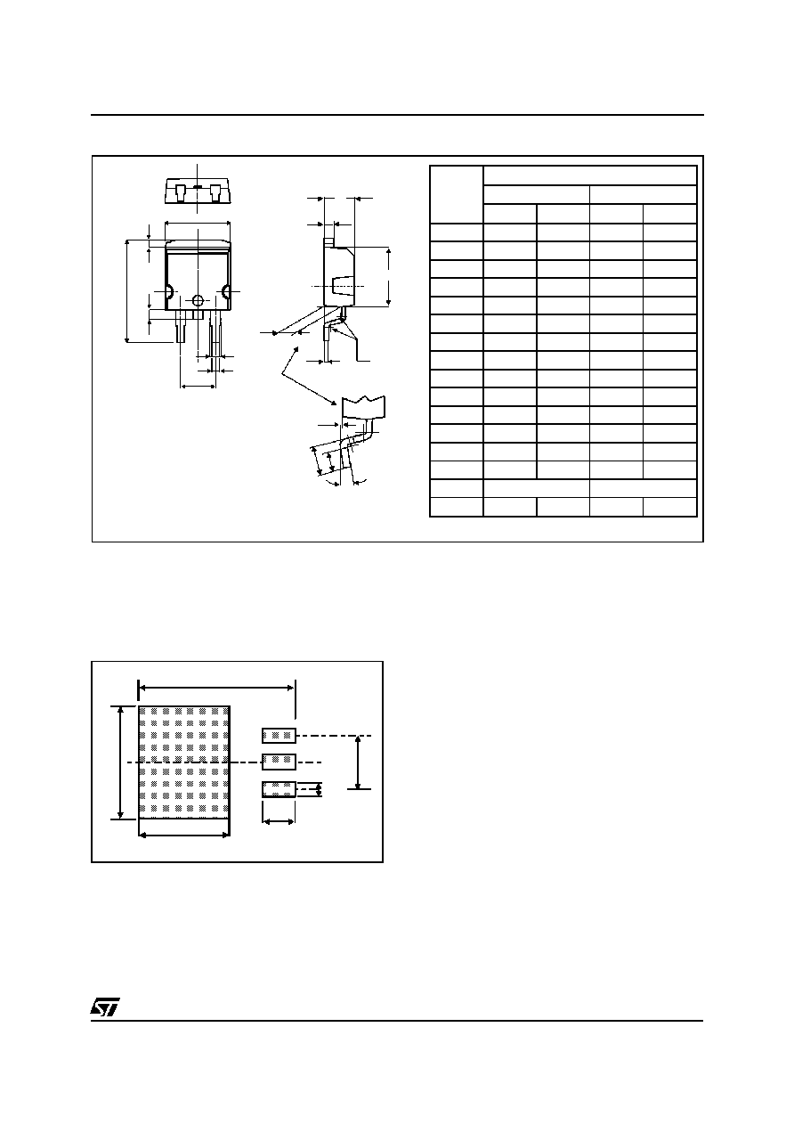
PACKAGE MECHANICAL DATA
D
2
PAK (Plastic)
A
C2
D
R
A2
M
V2
C
A1
G
L
L3
L2
B
B2
E
*
* FLAT ZONE NO LESSTHAN 2mm
REF.
DIMENSIONS
Millimeters
Inches
Min.
Max.
Min.
Max.
A
4.40
4.60
0.173
0.181
A1
2.49
2.69
0.098
0.106
A2
0.03
0.23
0.001
0.009
B
0.70
0.93
0.027
0.037
B2
1.14
1.70
0.045
0.067
C
0.45
0.60
0.017
0.024
C2
1.23
1.36
0.048
0.054
D
8.95
9.35
0.352
0.368
E
10.00
10.40
0.393
0.409
G
4.88
5.28
0.192
0.208
L
15.00
15.85
0.590
0.624
L2
1.27
1.40
0.050
0.055
L3
1.40
1.75
0.055
0.069
M
2.40
3.20
0.094
0.126
R
0.40 typ.
0.016 typ.
V2
0
∞
8
∞
0
∞
8
∞
8.90
3.70
1.30
5.08
16.90
10.30
FOOT PRINT (in millimeters)
STPR1620CG / STRP1620CT
5/6