STPS745D/F/G
Æ
June 1999 - Ed: 4D
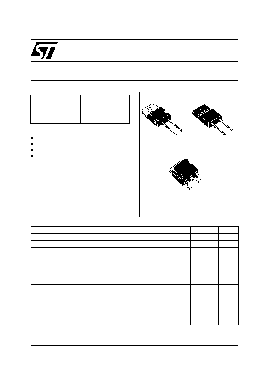
POWER SCHOTTKY RECTIFIER
I
F(AV)
7.5 A
V
RRM
45 V
Tj (max)
175
∞
C
V
F
(max)
0.57 V
MAIN PRODUCT CHARACTERISTICS
VERY SMALL CONDUCTION LOSSES
NEGLIGIBLE SWITCHING LOSSES
EXTREMELY FAST SWITCHING
INSULATED PACKAGE: ISOWATT220AC
Insulating voltage = 2000V DC
Capacitance = 12pF
FEATURES AND BENEFITS
Single Schottky rectifier suited for Switch Mode
Power Supply and high frequency DC to DC con-
verters.
Packaged either in TO-220AC, ISOWATT220AC
or D
2
PAK, this device is intended for use in low
voltage, high frequency inverters, free wheeling
and polarity protection applications.
DESCRIPTION
Symbol
Parameter
Value
Unit
V
RRM
Repetitive peak reverse voltage
45
V
I
F(RMS)
RMS forward current
20
A
I
F(AV)
Average forward current
= 0.5
TO-220AC /
D
2
PAK
Tc = 160
∞
C
7.5
A
ISOWATT220AC Tc = 145
∞
C
I
FSM
Surge non repetitive forward
current
tp = 10 ms sinusoidal
150
A
I
RRM
Repetitive peak reverse current
tp = 2
µ
s square F = 1kHz
1
A
I
RSM
Non repetitive peak reverse
current
tp = 100
µ
s square
2
A
Tstg
Storage temperature range
- 65 to + 175
∞
C
Tj
Maximum operating junction temperature *
175
∞
C
dV/dt
Critical rate of rise of reverse voltage
10000
V/
µ
s
ABSOLUTE RATINGS (limiting values)
ISOWATT220AC
STPS745F
A
K
TO-220AC
STPS745D
A
K
D
2
PAK
STPS745G
A
NC
K
* :
dPtot
dTj
<
1
Rth
(
j
-
a
)
thermal runaway condition for a diode on its own heatsink
1/7

Symbol
Parameter
Value
Unit
R
th (j-c)
Junction to case
TO-220AC / D
2
PAK
3.0
∞
C/W
ISOWATT220AC
5.5
THERMAL RESISTANCES
Symbol
Parameter
Tests Conditions
Min.
Typ.
Max.
Unit
I
R
*
Reverse leakage current
Tj = 25
∞
C
V
R
= V
RRM
100
µ
A
Tj = 125
∞
C
5
15
mA
V
F
*
Forward voltage drop
Tj = 125
∞
C
I
F
= 7.5 A
0.5
0.57
V
Tj = 25
∞
C
I
F
= 15 A
0.84
Tj = 125
∞
C
I
F
= 15 A
0.65
0.72
STATIC ELECTRICAL CHARACTERISTICS
Pulse test :
* tp = 380
µ
s,
< 2%
To evaluate the conduction losses use the following equation :
P = 0.42 x I
F(AV)
+ 0.020 I
F
2
(RMS)
STPS745D/F/G
2/7

1E-3
1E-2
1E-1
1E+0
0
20
40
60
80
100
120
t(s)
IM(A)
Tc=100
∞
C
Tc=50
∞
C
Tc=150
∞
C
I
M
t
=0.5
Fig. 3-1: Non repetitive surge peak forward
current versus overload duration (maximum
values) (TO-220AC and D
2
PAK).
1E-4
1E-3
1E-2
1E-1
1E+0
0.0
0.2
0.4
0.6
0.8
1.0
tp(s)
Zth(j-c)/Rth(j-c)
T
=tp/T
tp
Single pulse
= 0.1
= 0.2
= 0.5
Fig. 4-1: Relative variation of thermal transient
impedance junction to case versus pulse duration
(TO-220AC and D
2
PAK).
1E-3
1E-2
1E-1
1E+0
0
10
20
30
40
50
60
70
80
IM(A)
Tc=100
∞
C
Tc=50
∞
C
Tc=150
∞
C
t(s)
I
M
t
=0.5
Fig. 3-2: Non repetitive surge peak forward
current versus overload duration (maximum
values) (ISOWATT220AC).
1E-3
1E-2
1E-1
1E+0
1E+1
0.0
0.2
0.4
0.6
0.8
1.0
T
=tp/T
tp
tp(s)
Zth(j-c)/Rth(j-c)
Single pulse
= 0.1
= 0.2
= 0.5
Fig. 4-2: Relative variation of thermal transient
impedance junction to case versus pulse duration
(ISOWATT220AC).
0
25
50
75
100
125
150
175
0
1
2
3
4
5
6
7
8
9
Tamb(
∞
C)
IF(av)(A)
Rth(j-a)=15
∞
C/W
Rth(j-a)=Rth(j-c)
TO-220AC
ISOWATT220AB
Rth(j-a)=40
∞
C/W
T
=tp/T
tp
Fig.
2:
Average
current
versus
ambient
temperature (
= 0.5 ).
0
1
2
3
4
5
6
7
8
9
10
0
1
2
3
4
5
6
IF(av) (A)
PF(av)(W)
T
=tp/T
tp
= 1
= 0.5
= 0.2
= 0.1
= 0.05
Fig. 1: Average forward power dissipation versus
average forward current.
STPS745D/F/G
3/7

0
5
10
15
20
25
30
35
40
45
1E-1
1E+0
1E+1
1E+2
1E+3
1E+4
5E+4
VR(V)
IR(
µ
A)
Tj=150
∞
C
Tj=100
∞
C
Tj=125
∞
C
Tj=75
∞
C
Tj=50
∞
C
Tj=25
∞
C
Fig. 5: Reverse leakage current versus reverse
voltage applied (typical values).
1
2
5
10
20
50
100
200
500
1000
VR(V)
C(pF)
F=1MHz
Tj=25
∞
C
Fig. 6: Junction capacitance versus reverse
voltage applied (typical values).
0.0
0.2
0.4
0.6
0.8
1.0
1.2
1.4
1.6
0.1
1.0
10.0
100.0
VFM(V)
IFM(A)
Tj=25
∞
C
Tj=125
∞
C
Tj=125
∞
C
Typical values
Fig. 7: Forward voltage drop versus forward
current (maximum values).
0
2
4
6
8
10
12
14
16
18
20
0
10
20
30
40
50
60
70
80
S(Cu) (cm )
Rth(j-a) (
∞
C/W)
Fig. 8: Thermal resistance junction to ambient
versus copper surface under tab (Epoxy printed
circuit board, copper thickness: 35
µ
m).
STPS745D/F/G
4/7
