1/59
TDA7513T
June 2004
1
FEATURES
AM/FM TUNER FOR CAR-RADIO
INTEGRATED TUNING PLL
VARIABLE-BANDWITH FM IF FILTER (ISS)
FULLY INTEGRATED FM STEREO
DECODER
FULLY INTEGRATED FM NOISE BLANKER
HIGHLY INTEGRATED AUDIO PROCESSOR
2
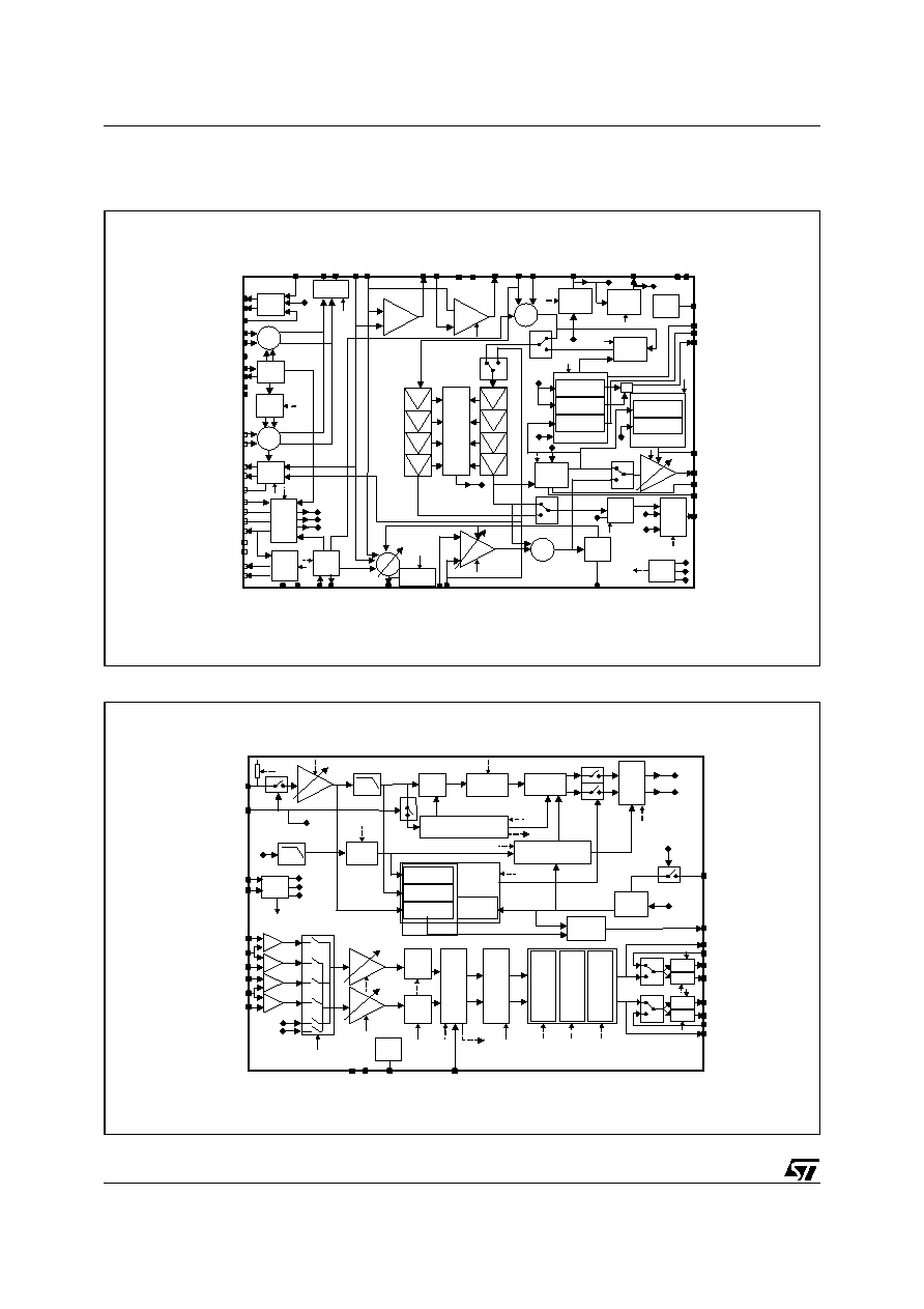
DESCRIPTION
The TDA7513T is the first device for car-radio ap-
plications that combines full RF front-end func-
tions with audio-processing capabilities.
As far as FM and AM functions are concerned , the
TDA7513T features front-end processing, includ-
ing the digital tuning PLL, IF processing with de-
modulation and variable-bandwidth IF filtering
(ISS), stop station and quality detection functions,
FM stereo decoding by means of a fully-integrat-
ed, adjustment-free dedicated PLL and, finally, FM
noise blanking. The FM stereo decoder and noise
blanker functions are realized entirely without ex-
ternal components.
The audio processor section comprises input se-
lectors for two quasi-differential external sources,
volume control, tone control (bass, mid and tre-
ble), balance and fading control to drive four out-
put channels. A soft mute function and an RDS
mute function are included to handle source
change as well as RDS AF search without abrupt
changes in the audio level.
Most of the parameters in the front-end section are
I
2
Cbus-driven and therefore under the control of
the car-radio maker. The I
2
C bus allows further-
more the user to realize the full electric alignment
of all the external coils, therefore removing the
need for hand-made or mechanical adjustments.
SINGLE-CHIP FM/AM TUNER WITH STEREO DECODER
AND AUDIO PROCESSOR
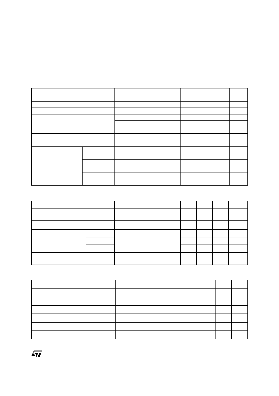
Figure 2. Pins Connection
1
2
3
5
6
4
7
8
9
10
31
11
32 33 34 35 36
75 74 73 72
70
71
69 68 67 66 65
55
54
53
51
50
52
60
59
58
56
57
AMAGC1IOUT
AMAGC1TC
AMMIX1IN2
TUNGND
VREF5V
AMMIX1IN1
FMAGCIOUT
FMMIX1IN2
RFGND
AMAGC1VOUT
FMMIX1IN1
XTALG
XTALD
DIGVCC
DIGGND
ISSTC
TUNQUALITY
DEVTC
VREF3V
APGND
APVCC
OUTRR
FMIFAMP1IN
FMIFAMP1OUT
FMIFAMPREF
TUNVCC
FMIFAMP2OUT
FMIFAMP2IN
FMMIX2IN1
FMMIX2IN2
AMMIX2OUT
AMAGC2TC
AMIF2AMPIN
SD
SCL
SDA
TUNEROUT
TUNERIN
FMMUTETC
MULTIPATHTC
RDSMUTE
AUDIOMUTE
SMETER
QUALITY
D03AU1527
26 27 28 29 30
76
FMNAGCIN
77
IFGND
78
MIX1OUT2
79
MIX1OUT1
80
IFVCC
LFREF
LFIN
LFHC
PLLVCC
PLLGND
21 22 23 24 25
49
48
46
45
47
IN1L
IN1COM
IN2R
IN2COM
IN1R
12
13
14
15
16
OSCGND
FMRFANDJ
FMANTADJ
FMWAGCIN
FMAGCVOUT
64 63 62 61
AMIF2AMPREF
SMETERTC
DEMGND
FMDEMREF
37 38 39 40
OUTRL
OUTFR
OUTFL
ACRIN
44
42
41
43
IN2L
ACLIN
ACROUT
ACLOUT
17
18
19
20
LFOUT
OSCVCC
VCOB
VCOE
REV. 1
Figure 1. Package
Table 1. Order Codes
Part Number
Package
TDA7513T
TQFP80
TQFP80

3/59
TDA7513T
Table 2. Pin Description
PIN
PIN NAME
PIN FUNCTION
1
VREF5V
5V reference
2
TUNGND
tuner general ground
3
AMMIX1IN1
am mix1 input
4
AMMIX1IN2
am mix1 input
5
AMAGC1TC
am agc1 filter capacitor
6
AMAGC1IOUT
am agc1 current output
7
AMAGC1VOUT
am agc1 voltage output
8
FMMIX1IN1
fm mix1 input
9
RFGND
rf ground
10
FMMIX1IN2
fm mix1 input
11
FMAGCIOUT
fm agc current output
12
FMWAGCIN
fm agc RF input
13
FMAGCVOUT
fm agc voltage output
14
FMANTADJ
fm antenna filter adjustment
15
FMRFANDJ
fm rf filter adjustment
16
OSCGND
vco ground
17
VCOE
am/fm vco emitter
18
VCOB
am/fm vco base
19
OSCVCC
vco supply (8V)
20
LFOUT
PLL loop filter output
21
LFREF
PLL loop filter reference
22
LFIN
PLL loop filter input
23
LFHC
PLL loop filter high-current input
24
PLLVCC
PLL back-end supply
25
PLLGND
PLL back-end ground
26
XTALG
ref osc gate
27
XTALD
ref osc drain
28
DIGVCC
digital dirty supply (8V)
29
DIGGND
digital ground
30
TUNQUALITY
tuner combined output of multipath and adjacent channel detectors
31
ISSTC
ISS time constant
32
DEVTC
deviation detector time constant
33
VREF3V
3V reference
34
APGND
audio processor/stereo decoder ground
35
APVCC
audio processor/stereo decoder supply (8V)
36
OUTRR
audio out
37
OUTRL
audio out
38
OUTFR
audio out
39
OUTFL
audio out
40
ACRIN
ac coupling right input

TDA7513T
4/59
PIN
PIN NAME
PIN FUNCTION
41
ACROUT
ac coupling right output
42
ACLIN
ac coupling left input
43
ACLOUT
ac coupling left output
44
IN2L
audio in2 left
45
IN2COM
audio in2 common
46
IN2R
audio in2 right
47
IN1R
audio in1 right
48
IN1COM
audio in1 common
49
IN1L
audio in1 left
50
TUNERIN
am audio/fm mpx input
51
TUNEROUT
am audio/fm mpx output
52
FMMUTETC
fm muting time constant capacitor
53
SDA
I2C bus data
54
SCL
I2C bus clock
55
SD
am/fm station detector output
56
SMETER
am/fm smeter output
57
QUALITY
quality output
58
AUDIOMUTE
audio mute control
59
RDSMUTE
rds mute control
60
MULTIPATHTC
multipath detector time constant
61
FMDEMREF
fm demodulator reference capacitor
62
DEMGND
fm demodulator ground
63
SMETERTC
am/fm smeter filtering capacitor
64
AMIF2AMPREF
am if2 amp feedback capacitor
65
AMIF2AMPIN
am if2 amp input
66
AMAGC2TC
am agc2 filter capacitor
67
AMMIX2OUT
am mix2 single-ended output
68
FMMIX2IN2
fm mix2 input
69
FMMIX2IN1
fm mix2 input
70
FMIFAMP2OUT
fm if1 amp2 output
71
FMIFAMP2IN
fm if1 amp2 input
72
TUNVCC
tuner general supply (8V)
73
FMIFAMPREF
fm if1 amps reference capacitor
74
FMIFAMP1OUT
fm if1 amp1 output
75
FMIFAMP1IN
fm if1 amp1 input
76
FMNAGCIN
fm agc IF input
77
IFGND
if1 ground
78
MIX1OUT2
am/fm mix1 output
79
MIX1OUT1
am/fm mix1 output
80
IFVCC
if1 supply (8V)
Table 2. Pin Description (continued)
5/59
TDA7513T
4
ELECTRICAL CHARACTERISTCS
4.1 FM (V
CC
= 8V; T
amb
= 25°C; V
sg
= 60dB
µ
V; fc = 98.1MHz; f
dev
= 40kHz; f
mod
= 1kHz unless otherwise
specified)
Table 3. General (audioprocessor all flat and stereo decoder input gain = 4dB )
Table 4. Mixer1
Table 5. Front-end Adjustment (VRFadj and VANTadj referred to VLFOUT)
Symbol
Parameter
Test Condition
Min
Typ
Max
Unit
US
Useable sensitivity
SNR = 40dB
0
dB
µ
V
SNR
Signal to Noise ratio
66
dB
LS
Limiting Sensitivity
Soft Mute OFF; @
Vout = -3dB
-4
dB
µ
V
THD
Total Harmonic Distortion
fdev = 40kHz
0.1
0.3
%
fdev = 75kHz
0.15
0.5
%
Vout
Audio output level
rms
375
mV
ISN
Interstation noise
Vout @ RF OFF; Soft Mute OFF
-13
dB
IFCS
IF Counter sensitivity
2
10
dB
µ
V
Icc
DC current
OSCVcc
5.7
mA
PLLVcc
1.9
mA
DIGVcc
9.8
mA
TUNVcc
50
mA
IF1Vcc
13.4
mA
APVcc
27.3
mA
Symbol
Parameter
Test Condition
Min
Typ
Max
Unit
Gv
conversion gain
from RFT secondary to IFT1
secondary loaded with 330
9
dB
IIP3
3
rd
order intercept point
referred to RFT secondary
dB
µ
V
CIFT1
IFT1
adjustment
capacitor
min
Between MIXOUT+ and MIXOUT-
0
pF
max
8.25
pF
step
0.55
pF
Rin
input resistance (single
ended)
FMMIX1IN+ and FMMIX1IN- w.r.t.
gnd
10
Symbol
Parameter
Test Condition
Min
Typ
Max
Unit
Vantadj
min
-40
%
max
40
%
step
1.29
%
VRFadj
min
-40
%
max
40
%
step
1.29
%