
TDA8178S
TV VERTICAL DEFLECTION BOOSTER
May 1993
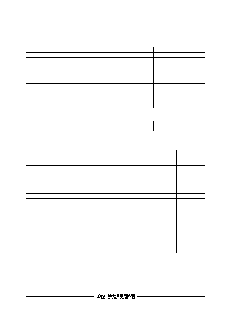
Output Stage Supply
Output
GND
Flyback Generator
Supply Voltage
Inverting Input
Tab connected to pin 4
7
6
5
4
3
2
1
Reference Voltage
8178S-01.EPS
PIN CONNECTIONS
HEPTAWATT
(Plastic Package)
ORDER CODE : TDA8178S
.
POWER AMPLIFIER
.
FLYBACK GENERATOR
.
THERMAL PROTECTION
.
REFERENCE VOLTAGE
DESCRIPTION
Designed for monitors and high performance TVs,
the TDA8178S vertical deflection booster delivers
flyback voltages up to 90V.
The TDA8178S operates with supplies up to 42V
and provides up to 2App output current to drive to
yoke.
The TDA8178Sis offered in HEPTAWATT package
1/6
ABSOLUTE MAXIMUM RATINGS
Symbol
Parameter
Value
Unit
V
S
Supply Voltage (pin 2)
50
V
V
5
, V
6
Flyback Peak Voltage
100
V
V
1
, V
7
Amplifier Input Voltage
+ V
S
I
O
Output Peak Current
Non-repetitive, t = 2ms
f = 50 or 60Hz, t
10
�
s
f = 50 or 60Hz, t > 10
�
s
2
2
1.8
A
I
3
Pin 3 DC at V
5
< V
2
Pin 3 Peak Flyback Current at f = 50 or 60Hz, t
fly
1.5ms
100
1.8
mA
A
P
to t
Total Power Dissipation at T
C
= 70
o
C
20
W
T
stg
Storage Temperature
- 40, + 150
o
C
T
j
Junction Temperature
0, +150
o
C
8178S-01.TBL
THERMAL DATA
Symbol
Parameter
Value
Unit
R
th (j-c)
Junction-case Thermal Resistance
Max.
3
o
C/W
8178S-02.TBL
ELECTRICAL CHARACTERISTICS
(V
S
= 42V, T
A
= 25
o
C, unless otherwise specified) (refer to the test circuits - see Figure 1 next page)
Symbol
Parameter
Test Conditions
Min.
Typ.
Max.
Unit
V
S
Operating Supply Voltage Range
10
42
V
I
2
Pin 2 Quiescent Current
I
3
= 0
I
5
= 0
10
20
mA
I
6
Pin 6 Quiescent Current
I
3
= 0
I
5
= 0
20
40
mA
I
1
Amplifier Bias Current
V
1
= 1V
- 0.2
- 1
�
A
V
3L
Pin 3 Saturation to GND
I
3
= 20mA
1.3
1.8
V
V
5
Quiescent Output Voltage
V
S
= 42V
R
a
= 3.9k
V
S
= 35V
R
a
= 5.6k
23.4
17
24.2
17.8
25
18.5
V
V
5L
Output Saturation Voltage to GND
I
5
= 1A
1.2
1.5
V
V
5H
Output Saturation Voltage to Supply
- I
5
= 1A
2.2
2.6
V
V
D5 - 6
Diode Forward Voltage between Pins 5-6
I
D
= 1A
1.5
3
V
V
D3 - 2
Diode Forward Voltage between Pins 3-2
I
D
= 1A
1.5
3
V
V
7
Internal Reference
2.1
2.2
2.3
V
V
7
/
V
S
Reference Voltage Drift versus V
S
V
S
= 24 to 42V
2
4
mV/V
K
T
Reference Voltage Drift versus T
j
T
j
= 0 to 125
o
C
K
T
=
V
7
10
6
T
j
V
7
100
150
ppm/
o
C
R
1
Input Resistance
200
k
T
j
Junction Temperature for Thermal
Shutdown
140
o
C
8178S-03.TBL
TDA8178S
3/6

FIGURE 1 : DC Test Circuits
2
6
5
1
7
4
+ V
S
I
6
I
2
I
1
1V
S1
a
b
V
7
10k
TDA8178S
8178S-04.EPS
S1 : (a) I
2
and I
6
, (b) I
1
Figure 1a : Measurement of I
1
, I
2
, I
6
, V
7
,
V
7
/
V
S
2
6
5
1
4
+ V
S
1V
V
5H
5
- I
TDA8178S
8178S-05.EPS
Figure 1b : Measurement of V
5H
2
6
5
1
4
+ V
S
V
Re
39k
5
TDA8178S
8178S-07.EPS
Figure 1d : Measurement of V
5
2
6
5
1
4
+ V
S
3
3V
V
5L
5
3
V
3L
S1
a
b
I or I
TDA8178S
8178S-06.EPS
S1 : (a)V
3L
, (b) V
5L
Figure 1c : Measurement of V
3L
, V
5L
TDA8178S
4/6

