 | –≠–ª–µ–∫—Ç—Ä–æ–Ω–Ω—ã–π –∫–æ–º–ø–æ–Ω–µ–Ω—Ç: TL1431ID | –°–∫–∞—á–∞—Ç—å:  PDF PDF  ZIP ZIP |

1 - Cathode
2 - Anode
3 - Anode
4 - N.C.
5 - N.C.
6 - Anode
7 - Anode
8 - Reference
Z
TO92
(Plastic Package)
.
ADJUSTABLE OUTPUT VOLTAGE :
V
ref
to 36V
.
SINK CURRENT CAPABILITY : 1 to 100mA
.
TYPICAL OUTPUT IMPEDANCE : 0.2
.
0.4% AND 0.25% VOLTAGE PRECISION
DESCRIPTION
The TL1431 is a programmable shunt voltage ref-
erence with guaranteed temperature stability over
the entire temperature range of operation.
The output voltage may be set to any value be-
tween V
ref
(approximately 2.5V) and 36V with two
external resistors.
The TL1431 operates with a wide current range
from 1 to 100mA with a typical dynamic impedance
of 0.2
.
PIN CONNECTIONS
8
7
6
5
1
2
3
4
SO8
(Top view)
Ca th o d e
Ano d e
Re fer e n c e
1
2
3
TO92
(Top view)
D
SO8
(Batwing Plastic Micropackage)
PROGRAMMABLE VOLTAGE REFERENCE
TL1431
ORDER CODES
Part number
Temperature Range
Package
Z
D
TL1431C/AC
-20
o
C, +70
o
C
∑
∑
TL1431I/AI
-40
o
C, +105
o
C
∑
∑
March 1998
1/8
ABSOLUTE MAXIMUM RATINGS
Symbol
Parameter
Value
Unit
V
KA
Cathode to Anode Voltage
37
V
I
K
Continuous Cathode Current Range
-100 to +150
mA
I
ref
Reference Input Current Range
-0.05 to +10
mA
T
oper
Operating Free-air Temperature Range
TL1431C/AC
TL1431I/AI
-20 to +70
-40 to +105
o
C
T
stg
Storage Temperature Range
-65 to +150
o
C
OPERATING CONDITIONS
Symbol
Parameter
Value
Unit
V
KA
Cathode to Anode Voltage
V
ref
to 36
V
I
K
Cathode Current
1 to 100
mA
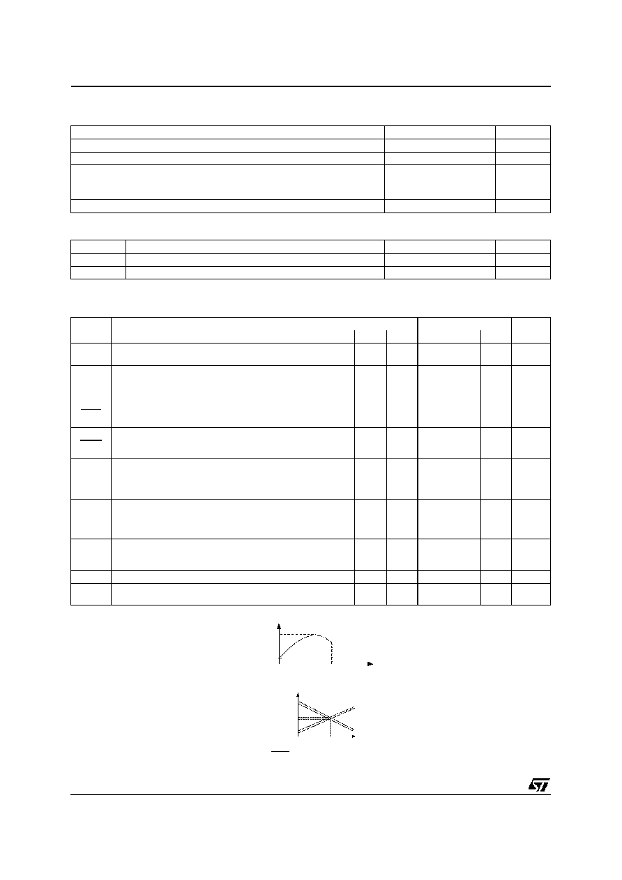
ELECTRICAL CHARACTERISTICS
T
amb
= 25
o
C (unless otherwise specified)
Symbol
Parameter
TL1431C
TL1431AC
Unit
Min.
Typ.
Max.
Min.
Typ.
Max.
V
ref
Reference Input Voltage - (figure 1)
V
KA
= V
ref
, I
K
= 10mA
T
amb
= 25
o
C
2.490
2.500
2.510
2.493
2.500
2.507
V
V
ref
Reference Input Voltage Deviation Over
Temperature Range - (figure 1, note1)
V
KA
= V
ref,
I
K =
10mA, T
min.
T
amb
T
max.
3
20
3
20
mV
V
ref
T
Temperature Coefficient of Reference Input
Voltage - (note 2)
V
KA
= V
ref
, I
K
= 10mA, T
min.
T
amb
T
max.
±
13
±
90
±
13
±
90
ppm/
o
C
V
ref
V
KA
Ratio of Change in Reference Input Voltage to
Change in Cathode to Anode Voltage - (figure 2)
I
K
= 10mA,
V
KA
= 36V to 3V
-2
-1.1
-2
-1.1
mV/V
Iref
Reference Input Current - (figure 2)
I
K
= 10mA, R
1
= 10k
, R
2
=
T
amb
= 25
o
C
T
min.
T
amb
T
max.
1.5
2.5
3
1.5
2.5
3
µ
A
I
ref
Reference Input Current Deviation Over
Temperature Range - (figure 2)
I
K
= 10mA, R
1
= 10k
, R
2
=
T
min.
T
amb
T
max.
0.2
1.2
0.2
1.2
µ
A
I
min
Minimum Cathode Current for Regulation - (figure
1)
V
KA
= V
ref
0.5
1
0.5
0.6
mA
I
off
Off-State Cathode Current - (figure 3)
180
500
180
500
nA
|Z
KA
|
Dynamic Impedance - (figure 1, note 3)
V
KA
= V
ref
,
I
K
= 1 to 100mA, f
1kHz
0.2
0.5
0.2
0.5
T1
T2
Tempe ra tur e
V
re f ma x.
V
re fm in.
Notes : 1.
V
ref
is defined as the difference between the maximum and minimum values obtained over the full temperature
range.
V
ref
= V
r ef max.
- V
ref min
2.
The temperature coefficient is defined as the slopes (positive and negative) of the voltage vs temperature limits whithin
which the reference voltage is guaranteed.
3.
The dynamic Impedance is defined as |Z
KA
|
=
V
KA
I
K
25 C
Te m pe ra ture
m a x
2.5V
min
-n
p
pm/
C
+ n
ppm
/ C
TL1431
2/8
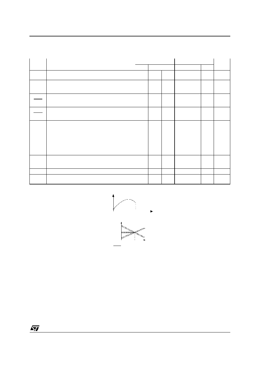
ELECTRICAL CHARACTERISTICS
T
amb
= 25
o
C (unless otherwise specified)
Symbol
Parameter
TL1431I
TL1431AI
Unit
Min.
Typ.
Max.
Min.
Typ.
Max.
V
ref
Reference Input Voltage - (figure 1)
V
KA
= V
ref
, I
K
= 10mA
T
amb
= 25
o
C
2.490
2.500
2.510
2.493
2.500
2.507
V
V
ref
Reference Input Voltage Deviation Over
Temperature Range - (figure 1, note1)
V
KA
= V
ref,
I
K =
10mA, T
min.
T
amb
T
max.
7
30
7
30
mV
V
ref
T
Temperature Coefficient of Reference Input
Voltage - (note 2)
V
KA
= V
ref
, I
K
= 10mA, T
min.
T
amb
T
max.
±
22
±
100
±
22
±
100
ppm/
o
C
V
ref
V
KA
Ratio of Change in Reference Input Voltage to
Change in Cathode to Anode Voltage - (figure 2)
I
K
= 10mA,
V
KA
= 36 to 3V
-1.1
-2
-1.1
-2
mV/V
Iref
Reference Input Current - (figure 2)
I
K
= 10mA, R
1
= 10k
, R
2
=
T
amb
= 25
o
C
T
min.
T
amb
T
max.
1.5
2.5
3
1.5
2.5
3
µ
A
I
ref
Reference Input Current Deviation Over
Temperature Range - (figure 2)
I
K
= 10mA, R
1
= 10k
, R
2
=
T
min.
T
amb
T
max.
0.5
1
0.8
1.2
µ
A
I
min
Minimum Cathode Current for Regulation
(figure 1)
V
KA
= V
ref
0.5
1
0.5
0.7
mA
I
off
Off-State Cathode Current - (figure 3)
180
500
180
500
nA
|Z
KA
|
Dynamic Impedance - (figure 1, note 3)
V
KA
= V
ref
,
I
K
= 1 to 100mA, f
1kHz
0.2
0.5
0.2
0.5
T1
T2
Tempera ture
V
re fma x.
V
ref min.
Notes : 1.
V
ref
is defined as the difference between the maximum and minimum values obtained over the full temperature
range.
V
ref
= V
ref max.
- V
ref min
2.
The temperature coefficient is defined as the slopes (positive and negative) of the voltage vs temperature limits whithin
which the reference voltage is guaranteed.
3.
The dynamic Impedance is defined as |Z
KA
|
=
V
KA
I
K
25 C
Te m pe ra ture
m a x
2.5V
min
-n
p pm
/
C
+ n
ppm
/ C
TL1431
3/8

V
KA
=
V
ref
(
1
+
R
1
R
2
) +
I
ref
. R1
V
KA
V
re f
Input
I
K
Figure 1 : Test Circuit for V
KA
= V
ref
V
KA
I
K
V
re f
I
re f
R
R
Input
1
2
Figure 2 : Test Circuit for V
KA
> V
ref
V
KA
Input
I
off
= 36V
Figure 3 : Test Circuit for I
off
Input
Vka
Vref
Ik=10mA
Iref
Output
10
µ
F
10
µ
F
15K
8.25K
230
Figure 4 : Test Circuit for Phase Margin and
Voltage Gain
TL1431
4/8

V
ka
= V
re f
V
ka
= V
ref
I
k
= 10mA
V
ka
= V
re f
= 2.5V
I
k
= 10mA
V
ka
= V
r ef
I
k
= 10mA
V
ka
= V
ref
= 2.5V
-40
-20
0
20
40
60
80
100
120
-14
-12
-10
-8
-6
-4
-2
0
Temperature (
∞
C)
Vref drift (m V)
DRIFT (mV) vs TEMPERATURE (
o
C)
CATHODE CURRENT vs CATHODE VOLTAGE
(detailed version)
-40
-20
0
20
40
60
80
100
120
0
0,02
0,04
0,06
0,08
0,1
Temperature (
∞
C)
Ioff (
µ
A)
OFF-STATE CATHODE CURRENT vs
TEMPERATURE
CATHODE CURRENT vs CATHODE VOLTAGE
-40
-20
0
20
40
60
80
100
120
1
1,2
1,4
1,6
1,8
2
Temperature (
∞
C)
Iref (
µ
A)
REFERENCE CURRENT vs TEMPERATURE
-40
-2 0
0
20
40
60
80
100
120
-1 ,6
-1 ,5
-1 ,4
-1 ,3
-1 ,2
-1 ,1
-1
-0 ,9
Temperature (
∞
C)
d(Vref) / d(Vka ) (mV/V)
RATIO OF CHANGE IN V
ref
TO CHANGE IN
V
KA
vs TEMPERATURE
TL1431
5/8