 | –≠–ª–µ–∫—Ç—Ä–æ–Ω–Ω—ã–π –∫–æ–º–ø–æ–Ω–µ–Ω—Ç: TL431ACZ | –°–∫–∞—á–∞—Ç—å:  PDF PDF  ZIP ZIP |
1/10
s
ADJUSTABLE OUTPUT VOLTAGE :
2.5 to 36V
s
SINK CURRENT CAPABILITY : 1 to 100mA
s
TYPICAL OUTPUT IMPEDANCE : 0.22
s
1% AND 2% VOLTAGE PRECISION
DESCRIPTION
The TL431 is a programmable shunt voltage
reference with guaranteed temperature stability
over the entire temperature range of operation.
The output voltage may be set to any value
between 2.5V and 36V with two external resistors.
The TL431 operates with a wide current range
from 1 to 100mA with a typical dynamic
impedance of 0.22
.
ORDER CODE
Z = TO92 Plastic package - also available in Bulk (Z), Tape & Reel (ZT)
and Ammo Pack (AP)
D = Small Outline Package (SO) - also available in Tape & Reel (DT)
PIN CONNECTIONS (top view)
Part
Number
Temperature
Range
Package
Z
D
TL431C/AC
0∞C, +70∞C
∑
∑
TL431I/AI
-40∞C, +105∞C
∑
∑
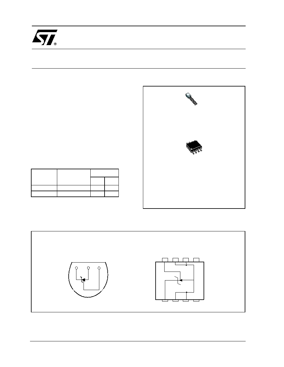
Z
TO92
(Plastic Package)
D
SO8
(Batwing Plastic Micropackage)
TO92
(Top view)
SO8
(Top view)
Cathode Anode Reference
1
2
3
8
7
6
5
1
2
3
4
1- Cathode
2- Anode
3- Anode.
4- N.C.
5- N.C.
6- Anode
7- Anode.
8- Reference
2-
TL431
PROGRAMMABLE VOLTAGE REFERENCE
March 2002
TL431
2/10
ABSOLUTE MAXIMUM RATINGS
OPERATING CONDITIONS
ELECTRICAL CHARACTERISTICS
T
amb
= 25∞C (unless otherwise specified)
1)
V
ref
is defined as the difference between the maximum and minimum values obtained over the full temperature range.
V
ref
= V
ref max.
- V
ref min.
2) The dynamic Impedance is definied as
ZKA
=
Symbol
Parameter
Value
Unit
V
KA
Cathode to Anode Voltage
37
V
I
k
Continuous Cathode Current Range
-100 to +150
mA
I
ref
Reference Input Current Range
-0.05 to +10
mA
p
d
Power Dissipation
1)
TO92
SO8 batwing
625
960
mW
T
stg
Storage Temperature Range
-65 to +150
∞C
1. Pd is calculated with T
amb
= +25∞C, T
j
= +150∞C and R
thja
= 200∞C/W for TO92 package
= 130∞C/W for SO8 batwing package
Symbol
Parameter
Value
Unit
V
KA
Cathode to Anode Voltage
V
ref
to 36
V
I
k
Cathode Current
1 to 100
mA
T
oper
Operating Free-air Temperature Range TL431C/AC
TL431I/AI
0 to +70
-40 to +105
∞C
Symbol
Parameter
TL431C
TL431AC
Unit
Min.
Typ.
Max.
Min.
Typ.
Max.
V
ref
Reference Input Voltage
V
KA
= V
ref
, I
k
= 10 mA T
amb
= 25∞C
T
min
T
amb
T
max
2.44
2.423
2.495
2.55
2.567
2.47
2.453
2.495
2.52
2.537
V
V
ref
Reference Input Voltage Deviation Over-
Temperature Range - note 1
V
KA
= V
ref
, I
k
= 10 mA,T
min
T
amb
T
max
3
17
3
15
mV
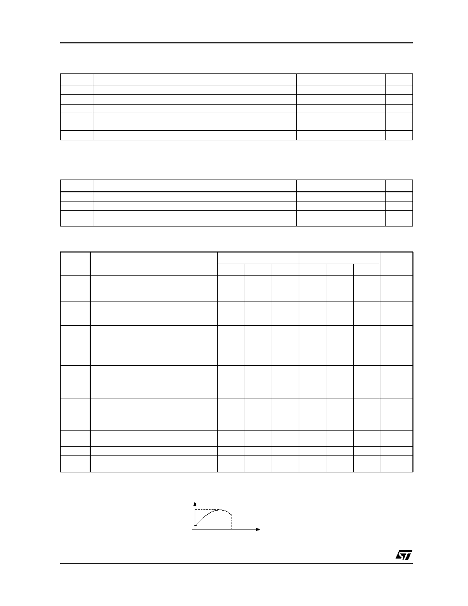
Ratio of Change in Reference Input
Voltage to Change in Cathode to Anode
Voltage - (figure 2)
Ik = 10mA
V
KA
= 10V to V
ref
V
KA
= 36V to 10V
-1.4
-1
-2.7
-2
-1.4
-1
-2.7
-2
mV/V
I
ref
Reference Input Current
Ik = 10mA, R1 = 10k
, R2 =
T
amb
= 25∞C
T
min
T
amb
T
max
1.8
4
5.2
1.8
4
5.2
µ
A
I
ref
Reference Input Current Deviation
Over Temperature Range
Ik = 10mA, R1 = 10k
, R2 =
T
min
T
amb
T
max
0.4 1.2
0.4
1.2
µ
A
I
min
Minimum Cathode Current for Regulation
V
KA
= V
ref
0.5
1
0.5
0.6
mA
I
off
Off-State Cathode Current
2.6
1000
2.6
1000
nA
Z
KA
Dynamic Impedance - note 2
V
KA
= V
ref
,
I
k
= 1 to100mA, f
1kHZ
0.22
0.5
0.22
0.5
Vref
Vka
------------
T1
T2
Temperature
V
ref max.
V
ref min.
V KA
I K
-----------------
TL431
3/10
ELECTRICAL CHARACTERISTICS
T
amb
= 25∞C (unless otherwise specified)
1)
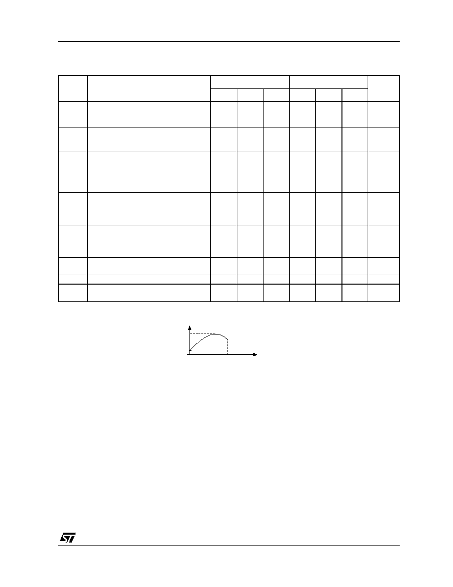
V
ref
is defined as the difference between the maximum and minimum values obtained over the full temperature range.
V
ref
= V
ref max.
- V
ref min.
2) The dynamic Impedance is definied as
ZKA
=
Symbol
Parameter
TL431I
TL431AI
Unit
Min.
Typ.
Max.
Min.
Typ.
Max.
V
ref
Reference Input Voltage
V
KA
= V
ref
, I
k
= 10 mA T
amb
= 25∞C
T
min
T
amb
T
max
2.44
2.41
2.495
2.55
2.58
2.47
2.44
2.495
2.52
2.55
V
V
ref
Reference Input Voltage Deviation Over-
Temperature Range - note 1
V
KA
= V
ref
, I
k
=10 mA,T
min
T
amb
T
max
7
30
7
30
mV
Ratio of Change in Reference Input
Voltage to Change in Cathode to Anode
Voltage
Ik = 10mA
V
KA
= 10V to V
ref
V
KA
= 36V to 10V
-1.4
-1
-2.7
-2
-1.4
-1
-2.7
-2
mV/V
I
ref
Reference Input Current
Ik = 10mA, R1 = 10k
, R2 =
T
amb
= 25∞C
T
min
T
amb
T
max
1.8
4
6.5
1.8
4
6.5
µ
A
I
ref
Reference Input Current Deviation
Over Temperature Range
Ik = 10mA, R1 = 10k
, R2 =
T
min
T
amb
T
max
0.8
2.5
0.8
1.2
µ
A
I
min
Minimum Cathode Current for Regulation
V
KA
= V
ref
0.5
1
0.5
0.7
mA
I
off
Off-State Cathode Current
2.6
1000
2.6
1000
nA
Z
KA
Dynamic Impedance note 2
V
KA
= V
ref
,
I
k
= 1 to100mA, f
1kHZ
0.22
0.5
0.22
0.5
Vref
V ka
------------
T1
T2
Temperature
V
ref max.
V
ref min.
V KA
I K
-----------------

TL431
4/10
Figure 1 : Test Circuit for V
KA
= V
REF
Figure 3 : Test Circuit for I
OFF
Figure 5 : Block diagram of TL1431
Figure 2 : Test Circuit for V
KA
> V
REF
Figure 4 : Test Circuit for Phase Margin and
Voltage Gain
Figure 6 : Test Circuit for Response time
Input
V
KA
V
REF
I
K
=10mA
Output
R
V
KA
=36V
I
OFF
Vref
Cathode
Anode
+
-
Vref
Vref
Cathode
Anode
+
-
Vref
V
KA
= V
REF
+ R1 x I
REF
1
R1
R2
--------
+
(
)
Input
V
KA
V
REF
I
K
R1
R2
I
REF
R
Output
Input
V
REF
I
K
=10mA
Outpu
t
10
µ
F
10
µ
F
15
k
8.
25
k
I
K
=1mA
Out
p
ut
0 mA
1 mA

TL431
5/10
Reference voltage vs Temperature
Reference voltage vs cathode current
Off-state cathode current vs temperature
Reference voltage vs cathode current
Reference current vs temperature
Ratio of change in V
REF
to change in V
KA
vs
Temperature
-40
-20
0
20
40
60
80
100
2.44
2.46
2.48
2.50
2.52
2.54
V
KA
= V
REF
I
K
= 10 mA
C
a
thode voltage V
KA
(V
)
Temperature (
∞
C)
-1
0
1
2
3
-2
-1
0
1
2
T
AMB
= +25
∞
C
C
a
thode current I
KA
(m
A
)
Cathode voltage V
KA
(V)
-40
-20
0
20
40
60
80
100
0.0
0.5
1.0
1.5
2.0
V
KA
= 36 V
V
REF
= 0 V
O
ff-state current I
OFF
(
µ
A)
Temperature (
∞
C)
-1
0
1
2
3
-50
-25
0
25
50
75
100
T
AMB
=+25
∞
C
C
a
thode current I
KA
(m
A
)
Cathode voltage V
KA
(V)
-40
-20
0
20
40
60
80
100
0.0
0.5
1.0
1.5
2.0
I
K
=10 mA
R
1
=10k
R2= +
R
e
ference current I
REF
(
µ
A)
Temperature ∞C
-40
-20
0
20
40
60
80
100
-2.0
-1.5
-1.0
-0.5
0.0
I
K
= 10 mA
V
REF
/
V
KA
(mV
/ V
)
Temperature (
∞
C)