
1/9
s
1.225V TYP OUTPUT VOLTAGE
s
ULTRA LOW OPERATING CURRENT : 65
µ
A
maximum at 25∞C
s
HIGH PRECISION @ 25∞C
+/- 2%
+/- 1%
+/- 0.5%
s
HIGH STABILITY WHEN USED WITH
CAPACITIVE LOADS
s
INDUSTRIAL TEMPERATURE RANGE:
-40 to +85∞C
s
150ppm/∞C MAXIMUM TEMPERATURE
COEFFICIENT
DESCRIPTION
The TS4041 is a low power shunt voltage
reference providing a stable 1.225V output
voltage over the industrial temperature range (-40
to +85∞C). Availabe in SOT23-3 surface mount
package, it can be designed in applications where
space saving is a critical issue.
The low operating current is a key advantage for
power restricted designs. In addition, the TS4041
is very stable and can be used in a broad range of
application conditions.
APPLICATION
s
Computers
s
Instrumentation
s
Battery chargers
s
Switch Mode Power Supply
s
Battery operated equipments
ORDER CODE
Z = TO92 Plastic package - also available in Bulk (Z), Tape & Reel (ZT)
and Ammo Pack (AP)
LT = Tiny Package (SOT23-3) - only available in Tape & Reel (LT)
PIN CONNECTIONS (top view)
Precision
TO92
SOT23-3
SOT23
Marking
2%
TS4041EIZ-1.2 TS4041EILT-1.2
L233
1%
TS4041DIZ-1.2 TS4041DILT-1.2
L232
0.5%
TS4041CIZ-1.2 TS4041CILT-1.2
L231
Single temperature range: -40 to +85∞C
Z
TO92
(Plastic Package)
L
SOT23-3L
(Plastic Micropackage)
TS4041
1.225V MICROPOWER SHUNT VOLTAGE REFERENCE
March 2002

TS4041
2/9
ABSOLUTE MAXIMUM RATINGS
OPERATING CONDITIONS
ELECTRICAL CHARACTERISTICS
TS4041E (2% Precision) T
amb
= 25∞C (unless otherwise specified)
Symbol
Parameter
Value
Unit
I
k
Reverse Breakdown Current
20
mA
I
f
Forward Current
10
mA
P
d
Power Dissipation
1)
SOT23-3
TO92
360
625
mW
T
std
Storage Temperature
-65 to +150
∞C
ESD
Human Body Model (HBM)
2
kV
Machine Model (MM)
200
V
T
lead
Lead Temperature (soldering, 10 seconds)
260
∞C
1. Pd has been calculated with T
amb
= 25∞C and T
j
= 150∞C and
Rthja = 200∞C/W for the TO92 package
Rthja = 340∞C/W for the SOT23-3L package
Symbol
Parameter
Value
Unit
I
min
Minimum Operating Current
65
µ
A
I
max
Maximum Operating Current
12
mA
T
oper
Operating Free Air Temperature Range
-40 to +85
∞C
Symbol
Parameter
Test Condition
Min.
Typ.
Max.
Unit
Vk
Reverse Breakdown Voltage
I
k
= 100
µ
A
1.200
1.225
1.250
V
Reverse Breakdown Voltage Tolerance
I
k
= 100
µ
A
-40∞C < T
amb
< +85∞C
-25
-36
+25
+36
mV
I
kmin
Minimum Operating Current
T
amb
= 25∞C
40
65
µ
A
-40∞C < T
amb
< +85∞C
70
V
ref
/
T Average Temperature Coefficient
I
k
= 100
µ
A
150
ppm/∞C
V
k
/
I
k
Reverse Breakdown Voltage Change
with Operating Current Range
I
kmin
< I
k
< 1mA
-40∞C < T
amb
< +85∞C
0.3
2
2.5
mV
1mA < I
k
< 12mA
-40∞C < T
amb
< +85∞C
2.5
8
10
R
ka
Static Impedance
I
k
= 45µA to 1mA
0.25
0.5
K
vh
Long Term Stability
I
k
= 100
µ
A, t = 1000hrs
120
ppm
En
Wide Band Noise
I
k
= 100
µ
A 10Hz < f < 10kHz
200
nV/
Hz
Note : Limits are 100% production tested at 25∞C. Limits over temperature are guaranteed through correlation and by design.

TS4041
3/9
ELECTRICAL CHARACTERISTICS
TS4041D (1% Precision) T
amb
= 25∞C (unless otherwise specified)
ELECTRICAL CHARACTERISTICS
TS4041C (0.5% Precision)T
amb
= 25∞C (unless otherwise specified)
Symbol
Parameter
Test Condition
Min.
Typ.
Max.
Unit
Vk
Reverse Breakdown Voltage
I
k
= 100
µ
A
1.213
1.225
1.237
V
Reverse Breakdown Voltage Tolerange
I
k
= 100
µ
A
-40∞C < T
amb
< +85∞C
-12
-25
+12
+25
mV
I
kmin
Minimum Operating Current
T
amb
= 25∞C
40
65
µ
A
-40∞C < T
amb
< +85∞C
70
V
ref
/
T Average Temperature Coefficient
I
k
= 100
µ
A
150
ppm/∞C
V
k
/
I
k
Reverse Breakdown Voltage Change
with Operating Current Range
I
kmin
< I
k
< 1mA
-40∞C < T
amb
< +85∞C
0.3
2
2.5
mV
1mA < I
k
< 12mA
-40∞C < T
amb
< +85∞C
2.5
8
10
R
ka
Static Impedance
I
k
= 45
µ
A to 1mA
0.25
0.5
K
vh
Long Term Stability
I
k
= 100
µ
A, t = 1000hrs
120
ppm
En
Wide Band Noise
I
k
= 100
µ
A 10Hz < f < 10kHz
200
nV/
Hz
Note : Limits are 100% production tested at 25∞C. Limits over temperature are guaranteed through correlation and by design.
Symbol
Parameter
Test Condition
Min.
Typ.
Max.
Unit
Vk
Reverse Breakdown Voltage
I
k
= 100
µ
A
1.219
1.225
1.231
V
Reverse Breakdown Voltage Tolerange
I
k
= 100
µ
A
-40∞C < T
amb
< +85∞C
-6
-16
+6
+16
mV
I
kmin
Minimum Operating Current
T
amb
= 25∞C
40
60
µ
A
-40∞C < T
amb
< +85∞C
65
V
ref
/
T Average Temperature Coefficient
I
k
= 100
µ
A
120
ppm/∞C
V
k
/
I
k
Reverse Breakdown Voltage Change
with Operating Current Range
I
kmin
< I
k
< 1mA
-40∞C < T
amb
< +85∞C
0.3
1.5
2
mV
1mA < I
k
< 12mA
-40∞C < T
amb
< +85∞C
2.5
6
8
R
ka
Static Impedance
I
k
= 45
µ
A to 1mA
0.25
0.5
K
vh
Long Term Stability
I
k
= 100
µ
A, t = 1000hrs
120
ppm
En
Wide Band Noise
I
k
= 100
µ
A 10Hz < f < 10kHz
200
nV/
Hz
Note : Limits are 100% production tested at 25∞C. Limits over temperature are guaranteed through correlation and by design.
TS4041
4/9
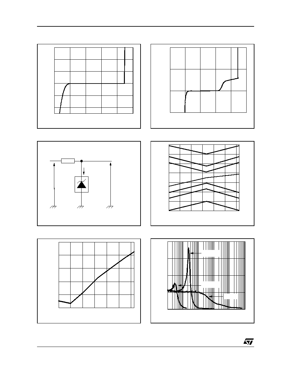
Reference voltage versus cathode current
Test circuit
Static impedance versus temperature
Reference voltage versus cathode current
Reference voltage versus Temperature
Noise voltage versus frequency
-1
-0.5
0
0.5
1
1.5
Reference voltage (V)
-8
-4
0
4
8
12
Ca
th
od
e c
u
rr
en
t (
m
A
)
Ik=(Vin-Vref)/R
Vout=Vref
R
-40
-20
0
20
40
60
80
Temperature (∞C)
0.2
0.21
0.22
0.23
0.24
0.25
St
at
i
c
i
m
pe
danc
e
(
O
h
m
s
)
-1
-0.5
0
0.5
1
1.5
Reference voltage (V)
-50
0
50
100
C
a
t
hode
cu
r
r
ent
(
µ
A)
-40
-20
0
20
40
60
80
Temperature (∞C)
1.19
1.2
1.21
1.22
1.23
1.24
1.25
1.26
C
a
t
hod
e vol
t
a
ge
(
V
)
+0.5%
-0.5%
-1%
+1%
-2%
+2%
0
1
10
100
1,000
10,000
Frequency (kHz)
0
200
400
600
800
No
is
e
v
o
lt
a
g
e
(
n
V
/
H
z
)
C
L
=10µF
C
L
=0µF
C
L
=100µF

TS4041
5/9
Pulse response for Ik=100µA
Pulse response for Ik=1mA
Test circuit for pulse response at Ik=100µA
Test circuit for pulse response at Ik=1mA
0
2
4
6
8
10
Time (µs)
3V
0V
1.225V
Input
Output
0V
0
2
4
6
8
10
Time (µs)
3V
0V
1.225V
Input
Output
0V
Ik=100µA
Ou
t
p
ut
18 K
Pulse
Generator
In
t
p
u
t
Ik=1mA
O
u
t
put
1.8 K
Pulse
Generator
In
tp
u
t