 | –≠–ª–µ–∫—Ç—Ä–æ–Ω–Ω—ã–π –∫–æ–º–ø–æ–Ω–µ–Ω—Ç: U426B-FP | –°–∫–∞—á–∞—Ç—å:  PDF PDF  ZIP ZIP |

U426B
Rev. A2, 15-Oct-98
1 (6)
Infrared Driver
Description
The U426B is an IR-driver IC for IR data communication.
The circuit contains a programmable constant current
source (DRV) to drive the IRED. The current is pro-
grammed by an external resistor (R
S
). With the internal
comparator (COMP) an external voltage can be moni-
tored. The low-power standby mode, controlled by means
of the WAKE input, makes the circuit well suited for bat-
tery-powered systems.
Features
D Programmable constant current 200 mA to 1.2 A
D Signal frequency up to 500 kHz
D Low-power standby mode
D Internal voltage comparator
D Wide voltage range 2.4 V to 12 V
Applications
D Keyless entry systems
D Remote control
D Wireless data communication
Ordering Information
Extended Type Number
Package
Remarks
U426B-FP
SO8
DRV
COMP
DATA
WAKE
MON≠O
MON≠I
R
S
V
Batt
Controller
U426B
95 9947
I
RED
Figure 1. Block diagram for an IR transmitter

U426B
Rev. A2, 15-Oct-98
2 (6)
Pin Description
8
7
6
5
1
2
3
4
U426B
DATA
MON≠I
MON≠O
V
S
GND
SHUNT
WAKE
95 9877
I
RED
Figure 2. Pinning
Pin
Symbol
Function
1
V
S
Supply voltage
8
GND
Circuit ground
2
DATA
Data input for switching the
IRED output current on and off
7
IRED
IR-LED output; when the data
input is high, this output supplies
the IR LED with the constant
current
6
SHUNT
The resistor at this pin adjusts
the IRED output current
3
MON-I
Voltage monitor input of the
internal comparator
4
MON-O
Voltage monitor output. This
open collector output is active
when the voltage at MON-I is
below the internal reference
V
3
= 525 mV typ.
5
WAKE
WAKE input. When being LOW,
the circuit is in standby mode. A
high level activates the circuit
Block Diagram
DATA
WAKE
MON≠O
MON≠I
V
S
95 9948
+
≠
V
Shunt
= 150 mV
typ.
DRV
≠
+
V
3
= 525 mV
typ.
COMP
Power
supply
SHUNT
GND
I
RED
COMP Monitoring comparator
DRV IRED constant current driver
Figure 3. Block diagram

U426B
Rev. A2, 15-Oct-98
3 (6)
Constant Current Driver (DRV)
The constant current driver converts the incoming data
pulses into adequate constant current pulses. A high level
applied to the data input causes a constant current flow
through the IR diode connected to the IRED output. This
current can be programmed via the external resistor (R
S
).
To calculate the output current, use the following
formula:
I
RED
+ 150 mV
R
S
Power Supply
The power-supply circuit generates the internal supply
voltage from an external voltage (V
S
= 2.4 V to 12 V).The
Pin V
S
is protected by an internal suppressor diode
against voltages above 13 V. The internal supply voltage
can be switched on/off with a high/low level at the WAKE
input. Setting WAKE to low level switches the circuit
from busy to standby mode which results in a very low
current consumption (2
mA). Every change between busy
and standby mode needs a latency of up to 1 ms. Data
transmission and voltage monitoring only takes place
while WAKE remains high.
Monitoring Comparator (COMP)
The monitoring comparator compares the voltage at Pin
MON-I to an internal reference voltage of V
3
= 525 mV
typ. The open collector output transistor is active if the
voltage at Pin MON-I falls below the internal threshold
voltage. The comparator can be used to monitor the pow-
er-supply battery.
t
SB
t
d
t
SB
WAKE
DATA
IRED
MON≠I
MON≠O
Standby
Standby
internal
circuit state
Output current
Busy
95 9878
Figure 4. Timing diagram

U426B
Rev. A2, 15-Oct-98
4 (6)
Absolute Maximum Ratings
Parameters
Symbol
Value
Unit
Supply voltage
Pin 1
V
S
13.4
V
Supply current
t < 10
ms
I
S
i
s
40
150
mA
mA
Input voltages
Pins 2, 3 and 5
Pin 6
V
I
V
S
1
V
V
Input currents
Pins 2, 3 and 5
I
I
1
mA
Output voltage
Pin 7
Pin 4
V
7
V
4
13.4
V
S
V
V
Output current
t < 100
ms
Pin 7
Pin 4
I
7
I
4
1.5
5
A
mA
Power dissipation T
amb
= 85
∞
C
SO8 : on PC board
on ceramic
on ceramic with silicon grease
P
tot
P
tot
P
tot
150
250
430
mW
mW
mW
Junction temperature
T
j
125
∞
C
Ambient temperature range
T
amb
≠40 to 85
∞
C
Storage temperature range
T
stg
≠40 to 150
∞
C
Thermal Resistance
Parameters
Symbol
Value
Unit
Junction ambient
SO8: on PC board
on ceramic
on ceramic with silicon grease
R
thJA
R
thJA
R
thJA
220
140
80
K/W
K/W
K/W
Electrical Characteristics
V
S
= 6 V, T
amb
= 25
∞
C, reference point Pin 8, unless otherwise specified
Parameters
Test Conditions / Pins
Symbol
Min.
Typ.
Max.
Unit
Supply current
Pin 1
Supply voltage
Pin 1
V
S
2.4
12
V
Standby current
I
I
2
mA
Wake-up current
Without pulse
I
I
1.5
mA
Overvoltage protection
I
1
= 20 mA
V
S
13
V
DATA
Pin 2
Input signal
High
Low
V
2
V
2
3
1.6
3.6
2.1
4.2
2.6
V
V
Common-mode input
0
V
S
V
Rise time
t
r
500
ns
Fall time
t
f
500
ns
Signal frequency
f
500
kHz
Input current
I
2
100
mA
MON-I
Pin 3
Reverse current
V
3
= 0 V
I
r
0.8
mA
Input voltage HIGH
Input voltage LOW
MON-I on
MON-O off
V
3
V
3
485
515
525
545
555
580
mV
mV
Hysteresis
4
%
Temperature coefficient
TC
100
mA/K
Input current
V
3
= 6 V
I
3
0.3
mA
U426B
Rev. A2, 15-Oct-98
5 (6)
Electrical Characteristics (continued)
V
S
= 6 V, T
amb
= 25
∞
C, reference point Pin 8, unless otherwise specified
Parameters
Test Conditions / Pins
Symbol
Min.
Typ.
Max.
Unit
MON-O
Pin 4
Output current
V
4
200 mV
I
4
1
mA
Output current
V
4
400 mV
I
4
3
mA
Reverse current
V
4
6 V
I
r
0.2
mA
Output voltage HIGH
V
S
V
Saturation voltage
I
4
= 1 mA
V
sat
200
mV
WAKE
Pin 5
Input current
V
5
= 6 V
V
5
= 0 V
I
5
I
5
80
±
0.2
mA
mA
Input voltage HIGH
Input voltage LOW
Busy
Standby
V
5
V
5
0
V
S
0.2
V
V
SHUNT
Pin 6
Output current IRED
V
S
= 2.4 V; R
S
= 0.62
W
V
S
= 6.0 V; R
S
= 0.62
W
V
S
= 12 V; R
S
= 0.62
W
V
S
= 6 V; R
S
= 0.11
W
V
S
= 12 V; R
S
= 0.11
W
I
7
I
7
I
7
I
7
I
7
205
220
235
1.25
1.3
245
265
275
1.5
1.55
mA
mA
mA
A
A
Shunt voltage
V
2
= V
S
= 6 V;
R
S
= 0.11
W
V
Shunt
140
150
160
mV
Temperature coefficient
T
amb
= ≠40 to 85
∞
C
T
C
40
mV/K
IRED
Pin 7
Output voltage
V
2
= V
S
= 6 V; I
7
= 1 A
V
out
1000
mV
Output voltage
V
2
=0 V; I
7
= 0
V
out
12
13.2
V
Reverse current
V
2
=0 V; V
7
= 6 V
I
r
1
mA
Rise/fall time
t
r
300
ns
Delay time
Pin 2 to Pin 7
t
d
1
ms
Standby/busy
t
SB
1
ms
Busy/standby
t
BS
1
ms
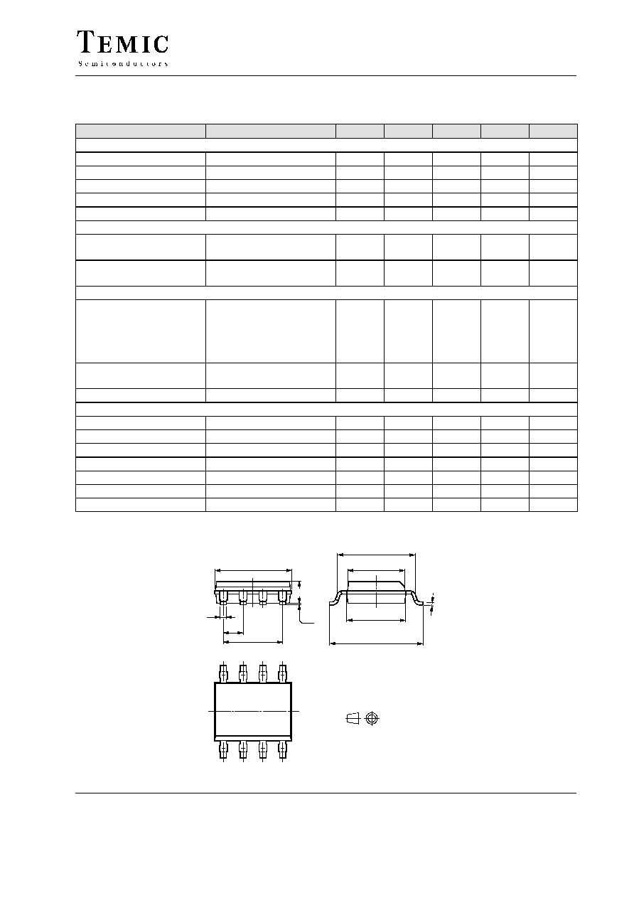
Package Information
13034
technical drawings
according to DIN
specifications
Package SO8
Dimensions in mm
5.00
4.85
0.4
1.27
3.81
1.4
0.25
0.10
5.2
4.8
3.7
3.8
6.15
5.85
0.2
8
5
1
4