Features
Æ Direct clock/calendar replace-
ment for IBM
Æ
AT-compatible
computers and other applications
Æ Functionally compatible with the
DS1287/DS1287A and MC146818A
Æ 114 bytes of general nonvolatile
storage
Æ Integral lithium cell and crystal
Æ 160 ns cycle time allows fast bus
operation
Æ Selectable Intel or Motorola bus
timing
Æ 14 bytes for clock/calendar and
control
Æ BCD or binary format for clock
and calendar data
Æ Time of day in seconds, minutes,
and hours
-
12- or 24-hour format
-
Optional daylight saving
adjustment
Æ Calendar in day of the week, day
of the month, months, and years
with automatic leap-year adjust-
ment
Æ Programmable square wave out-
put
Æ Three individually maskable in-
terrupt event flags:
-
Periodic rates from 122
µ
s to
500 ms
-
Time-of-day alarm once per
second to once per day
-
End-of-clock update cycle
Æ Better than one minute per
month clock accuracy
General Description
The CMOS bq3287/bq3287A is a
low-power microprocessor periph-
eral providing a time-of-day clock
and 100-year calendar with alarm
features and battery operation.
O t h e r f e a t u r e s i n cl u d e t h r e e
maskable interrupt sources, square-
wave output, and 114 bytes of gen-
e r a l n o n volatile storage. The
bq3287A version is identical to the
bq3287, with the addition of the RAM
clear input.
The bq3287 is a fully compatible
r e a l - t i m e c l o c k f o r I B M A T-
compatible computers and other ap-
p l i c a t i o n s. T h e b q 3 2 8 7 w r i t e -
protects the clock, calendar, and
storage registers during power fail-
ure. The integral backup energy
source then maintains data and op-
erates the clock and calendar.
As shipped from Benchmarq, the
real time clock is turned off to maxi-
mize battery capacity for in-system
operation.
The bq3287 is functionally equiva-
lent to the bq3285, except that the
battery (16, 20) and crystal (2, 3)
pins are not accessible. These pins
are connected internally to a coin
cell and quartz crystal. The coin cell
is sized to provide 10 years of data
retention and clock operation in the
absence of power. For a complete de-
scription of features, operating con-
ditions, electrical characteristics,
bus timing, and pin descriptions, see
the bq3285 data sheet.
1
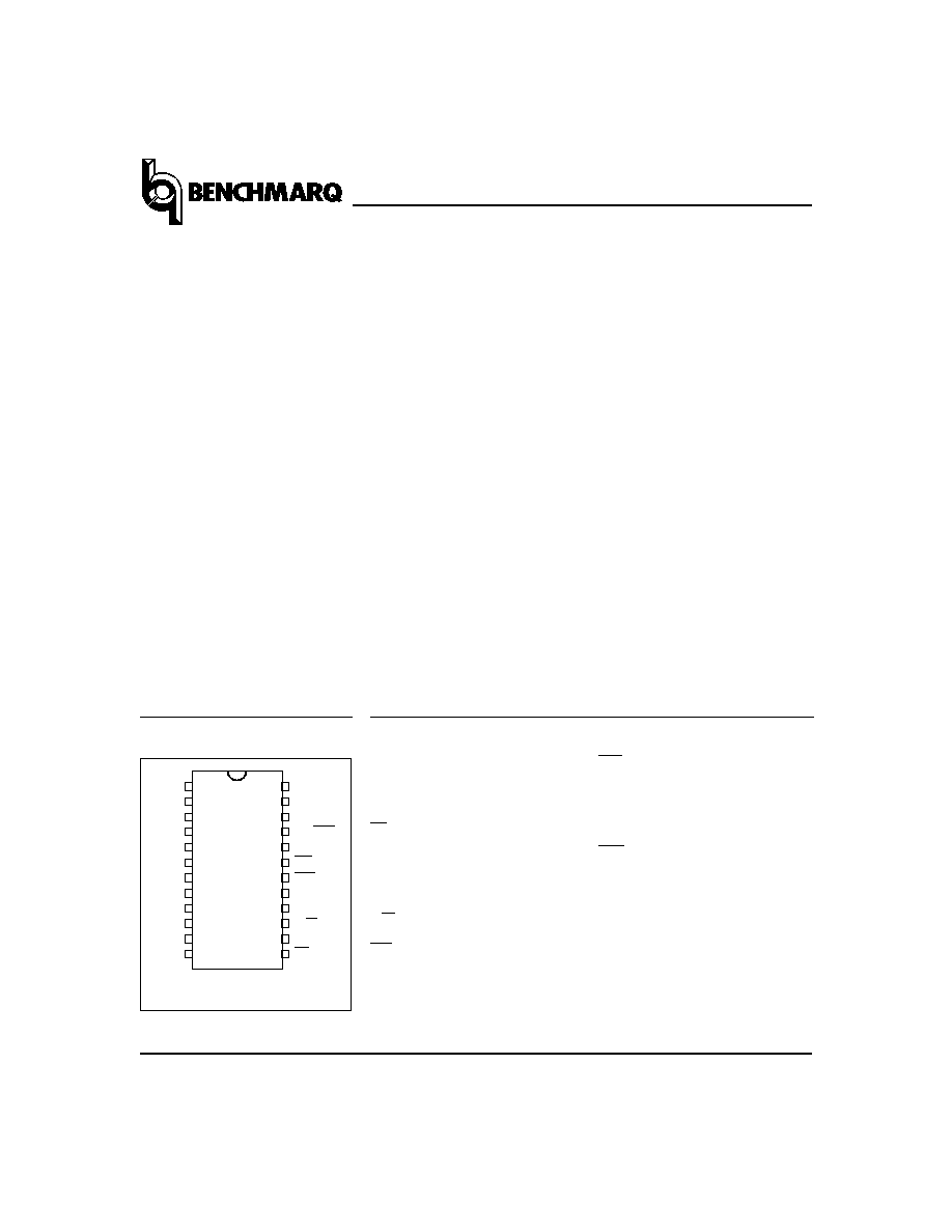
Pin Names
AD
0
≠AD
7
Multiplexed address/data
input/output
MOT
Bus type select input
CS
Chip select input
AS
Address strobe input
DS
Data strobe input
R/W
Read/write input
INT
Interrupt request output
1
PN328701.eps
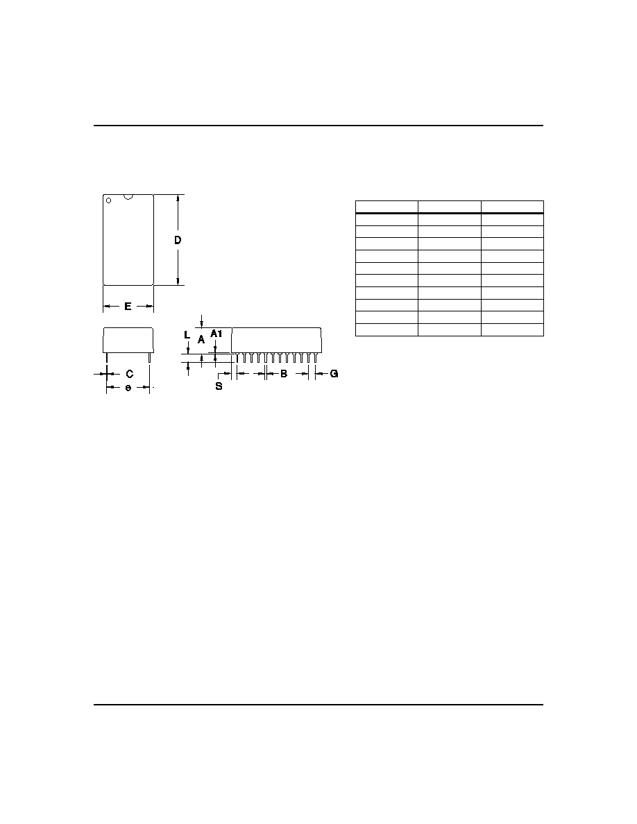
24-Pin DIP Module
2
3
4
5
6
7
8
24
23
22
21
20
19
18
17
9
10
16
15
11
12
14
13
VCC
SQW
NC
NC
INT
RST
DS
NC
R/W
AS
CS
MOT
NC
NC
AD0
AD1
AD2
AD3
AD4
AD5
AD6
AD7
VSS
NC/RCL
Sept. 1996 D
RST
Reset input
SQW
Square wave output
NC
No connect
RCL
RAM clear input
(bq3287A only)
V
CC
+5V supply
V
SS
Ground
Pin Connections
bq3287/bq3287A
Real-Time Clock (RTC) Module
2
Sept. 1996 D
Recommended DC Operating Conditions
(TA = TOPR)
Symbol
Parameter
Minimum
Typical
Maximum
Unit
V
CC
Supply voltage
4.5
5.0
5.5
V
V
SS
Supply voltage
0
0
0
V
V
IL
Input low voltage
-0.3
-
0.8
V
V
IH
Input high voltage
2.2
-
V
CC
+ 0.3
V
Note:
Typical values indicate operation at T
A
= 25∞C.
Absolute Maximum Ratings
Symbol
Parameter
Value
Unit
Conditions
V
CC
DC voltage applied on V
CC
relative to V
SS
-0.3 to 7.0
V
V
T
DC voltage applied on any pin excluding V
CC
relative to V
SS
-0.3 to 7.0
V
V
T
V
CC
+ 0.3
T
OPR
Operating temperature
0 to +70
∞C
Commercial
-20 to +70
∞C
Extended "I"
T
STG
Storage temperature
-40 to +70
∞C
Commercial
-40 to +70
∞C
Extended "I"
T
BIAS
Temperature under bias
-10 to +70
∞C
Commercial
-20 to +70
∞C
Extended "I"
T
SOLDER
Soldering temperature
260
∞C
For 10 seconds
Note:
Permanent device damage may occur if Absolute Maximum Ratings are exceeded. Functional opera-
tion should be limited to the Recommended DC Operating Conditions detailed in this data sheet. Expo-
sure to conditions beyond the operational limits for extended periods of time may affect device reliability.
DC Electrical Characteristics
(TA = TOPR, VCC = 5V
±
10%)
Symbol
Parameter
Minimum
Typical
Maximum
Unit
Conditions/Notes
I
LI
Input leakage current
-
-
±
1
µ
A
V
IN
= V
SS
to V
CC
I
LO
Output leakage current
-
-
±
1
µ
A
AD
0
≠AD
7
, INT and SQW
in high impedance
V
OH
Output high voltage
2.4
-
-
V
I
OH
= -1.0 mA
V
OL
Output low voltage
-
-
0.4
V
I
OL
= 4.0 mA
I
CC
Operating supply current
-
7
15
mA
Min. cycle, duty = 100%,
I
OH
= 0mA, I
OL
= 0mA
V
SO
Supply switch-over voltage
-
3.0
-
V
V
PFD
Power-fail-detect voltage
4.0
4.17
4.35
V
I
RCL
Input current when RCL = V
SS
-
-
185
µ
A
Internal 30K pull-up
(bq3287A only)
I
MOTH
Input current when MOT =
V
CC
-
-
-185
µ
A
Internal 30K pull-down
Note:
Typical values indicate operation at T
A
= 25∞C, V
CC
= 5V.
bq3287/bq3287A
3
Sept. 1996 D
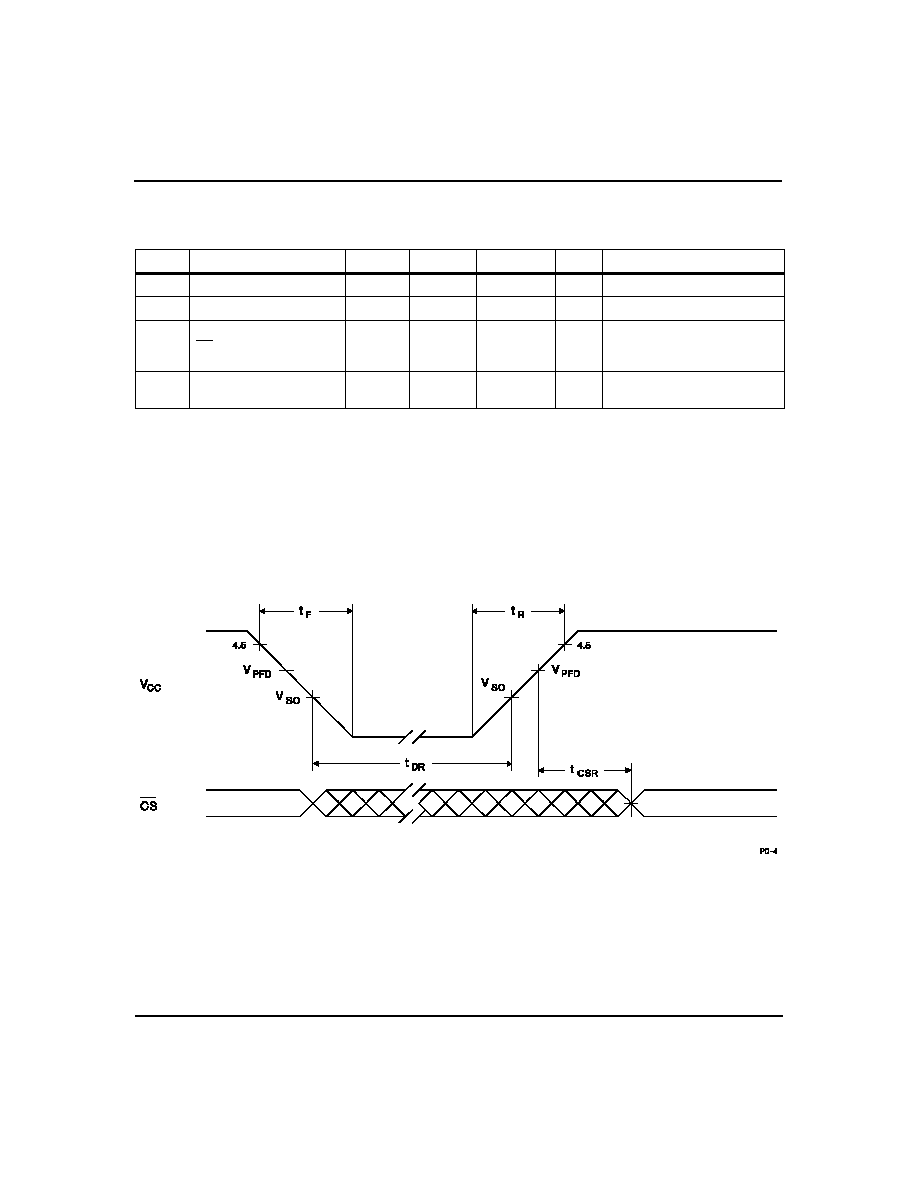
Power-Down/Power-Up Timing
(TA = TOPR)
Symbol
Parameter
Minimum
Typical
Maximum
Unit
Conditions
t
F
V
CC
slew from 4.5V to 0V
300
-
-
µ
s
t
R
V
CC
slew from 0V to 4.5V
100
-
-
µ
s
t
CSR
CS at V
IH
after power-up
20
-
200
ms
Internal write-protection
period after V
CC
passes V
PFD
on power-up.
t
DR
Data-retention and time-
keeping time
10
-
-
years
T
A
= 25∞C.
Note:
Clock accuracy is better than
±
1 minute per month at 25∞C for the period of t
DR
.
Caution:
Negative undershoots below the absolute maximum rating of -0.3V in battery-backup mode
may affect data integrity.
Power-Down/Power-Up Timing
bq3287/bq3287A
5
Sept. 1996 D
bq3287/bq3287A
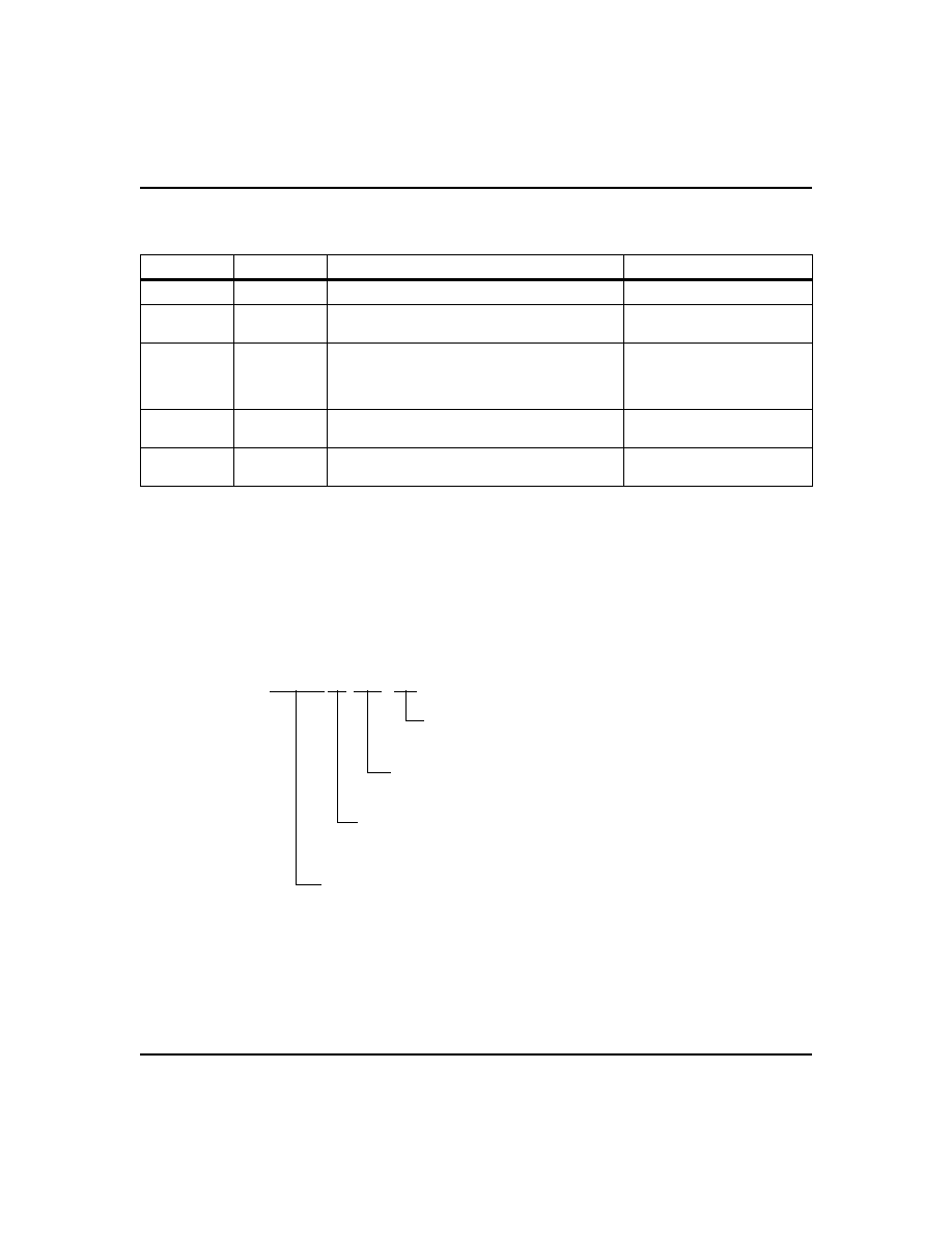
Ordering Information
Data Sheet Revision History
Change No.
Page No.
Description
Nature of Change
1
1
Address strobe input
Clarification
1
2
Power-fail detect voltage V
PFD
Was 4.1 min, 4.25 max;
is 4.0 min, 4.35 max
2
1
Was : "As shipped from Benchmarq, the backup cell
is electrically isolated from the memory. "
Is: "As shipped from Benchmarq, the backup cell is
electrically isolated from the active circuitry. "
Clarification
2
2, 4
Changed temperature from N (industrial, -40 to
+85∞C) to I (extended, -20 to +70∞C)
Specification change
3
2
I
RCL
max. was 275; is now 185. Pull-up = 30K
I
MOTH
max. was -275; is now -185. Pull-down = 30K Changed values
Notes:
Change 1 = Nov. 1992 B changes from June 1991 A.
Change 2 = Nov. 1995 C changes from Nov. 1992 B.
Change 3 = Sept. 1996 D changes from Nov. 1995 C.
*Contact factory for availability.
bq3287
MT -
Package Option:
MT = T-type module
Device:
bq3287 Real-Time Clock Module
RAM Clear Option:
A = RAM clear on pin 21
no mark = No connect on pin 21
Temperature:
blank = Commercial (0 to +70∞C)
I = Extended* (-20 to +70∞C)