
LM285 1.2, LM385 1.2, LM385B 1.2
MICROPOWER VOLTAGE REFERENCES
SLVS075H - APRIL 1989 - REVISED FEBRUARY 2005
1
POST OFFICE BOX 655303
∑
DALLAS, TEXAS 75265
D
Operating Current Range
- LM285 . . . 10
µ
A to 20 mA
- LM385 . . . 15
µ
A to 20 mA
- LM385B . . . 15
µ
A to 20 mA
D
1% and 2% Initial Voltage Tolerance
D
Reference Impedance
- LM385 . . . 1
Max at 25
∞
C
- All Devices . . . 1.5
Max Over Full
Temperature Range
D
Very Low Power Consumption
D
Applications
- Portable Meter References
- Portable Test Instruments
- Battery-Operated Systems
- Current-Loop Instrumentation
- Panel Meters
D
Interchangeable With Industry Standard
LM285-1.2 and LM385-1.2
description/ordering information
These micropower, two-terminal, band-gap voltage references operate over a 10-
µ
A to 20-mA current range
and feature exceptionally low dynamic impedance and good temperature stability. On-chip trimming provides
tight voltage tolerance. The band-gap reference for these devices has low noise and long-term stability.
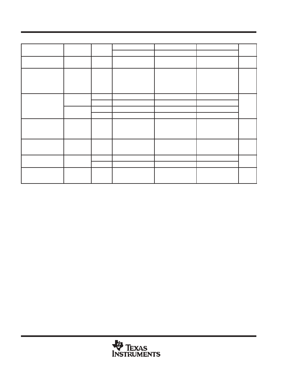
ORDERING INFORMATION
TA
VZ
TOLERANCE
PACKAGE
ORDERABLE
PART NUMBER
TOP-SIDE
MARKING
SOIC (D)
Tube of 75
LM385D-1-2
385-12
SOIC (D)
Reel of 2000
LM385DR-1-2
385-12
SOP (PS)
Reel of 2000
LM385PSR-1-2
L385-12
2%
TO-226 / TO-92 (LP)
Tube of 1000
LM385LP-1-2
385-12
2%
TO-226 / TO-92 (LP)
Reel of 2000
LM385LPR-1-2
385-12
TSSOP (PW)
Tube of 150
LM385PW-1-2
385-12
0
∞
C to 70
∞
C
TSSOP (PW)
Reel of 2000
LM385PWR-1-2
385-12
0 C to 70 C
SOIC (D)
Tube of 75
LM385BD-1-2
385B12
SOIC (D)
Reel of 2000
LM385BDR-1-2
385B12
1%
TO-226 / TO-92 (LP)
Tube of 1000
LM385BLP-1-2
385-12
1%
TO-226 / TO-92 (LP)
Reel of 2000
LM385BLPR-1-2
385-12
TSSOP (PW)
Tube of 150
LM385BPW-1-2
385B12
TSSOP (PW)
Reel of 2000
LM385BPWR-1-2
385B12
SOIC (D)
Tube of 75
LM285D-1-2
285-12
-40
∞
C to 85
∞
C
1%
SOIC (D)
Reel of 2000
LM285DR-1-2
285-12
-40 C to 85 C
1%
TO-226 / TO-92 (LP)
Tube of 1000
LM285LP-1-2
285-12
Package drawings, standard packing quantities, thermal data, symbolization, and PCB design guidelines are available
at www.ti.com/sc/package.
Copyright
2005, Texas Instruments Incorporated
PRODUCTION DATA information is current as of publication date.
Products conform to specifications per the terms of Texas Instruments
standard warranty. Production processing does not necessarily include
testing of all parameters.
Please be aware that an important notice concerning availability, standard warranty, and use in critical applications of
Texas Instruments semiconductor products and disclaimers thereto appears at the end of this data sheet.
1
2
3
4
8
7
6
5
NC
NC
NC
ANODE
CATHODE
NC
NC
NC
LM285-1.2 . . . D PACKAGE
LM385-1.2 . . . D, PS, OR PW PACKAGE
LM385B-1.2 . . . D OR PW PACKAGE
(TOP VIEW)
NC - No internal connection
LM285-1.2, LM385-1.2, LM385B-1.2 . . . LP PACKAGE
(TOP VIEW)
NC - No internal connection
NC
CATHODE
ANODE

LM285 1.2, LM385 1.2, LM385B 1.2
MICROPOWER VOLTAGE REFERENCES
SLVS075H - APRIL 1989 - REVISED FEBRUARY 2005
2
POST OFFICE BOX 655303
∑
DALLAS, TEXAS 75265
description/ordering information (continued)
The design makes these devices exceptionally tolerant of capacitive loading and, thus, easier to use in most
reference applications. The wide dynamic operating temperature range accommodates varying current
supplies, with excellent regulation.
The extremely low power drain of this series makes them useful for micropower circuitry. These voltage
references can be used to make portable meters, regulators, or general-purpose analog circuitry, with battery
life approaching shelf life. The wide operating current range allows them to replace older references with
tighter-tolerance parts.
symbol
ANODE
CATHODE
schematic
CATHODE
Q13
Q12
Q7
Q4
600 k
7.5 k
ANODE
200 k
50 k
300 k
Q14
20 pF
20 pF
Q11
Q10
Q9
Q5
Q3
Q1
Q2
Q8
Q6
60 k
500
100 k
NOTE A: Component values shown are nominal.

LM285 1.2, LM385 1.2, LM385B 1.2
MICROPOWER VOLTAGE REFERENCES
SLVS075H - APRIL 1989 - REVISED FEBRUARY 2005
3
POST OFFICE BOX 655303
∑
DALLAS, TEXAS 75265
absolute maximum ratings over operating free-air temperature range (unless otherwise noted)
Reverse current, I
R
30 mA
. . . . . . . . . . . . . . . . . . . . . . . . . . . . . . . . . . . . . . . . . . . . . . . . . . . . . . . . . . . . . . . . . . . . . .
Forward current, I
F
10 mA
. . . . . . . . . . . . . . . . . . . . . . . . . . . . . . . . . . . . . . . . . . . . . . . . . . . . . . . . . . . . . . . . . . . . . . .
Package thermal impedance,
JA
(see Notes 1 and 2): D package
97
∞
C/W
. . . . . . . . . . . . . . . . . . . . . . . . . . . .
LP package
140
∞
C/W
. . . . . . . . . . . . . . . . . . . . . . . . . .
PS package
95
∞
C/W
. . . . . . . . . . . . . . . . . . . . . . . . . . .
PW package
149
∞
C/W
. . . . . . . . . . . . . . . . . . . . . . . . .
Operating virtual junction temperature, T
J
150
∞
C
. . . . . . . . . . . . . . . . . . . . . . . . . . . . . . . . . . . . . . . . . . . . . . . . . . .
Lead temperature 1,6 mm (1/16 inch) from case for 10 seconds
260
∞
C
. . . . . . . . . . . . . . . . . . . . . . . . . . . . . . .
Storage temperature range, T
stg
-65
∞
C to 150
∞
C
. . . . . . . . . . . . . . . . . . . . . . . . . . . . . . . . . . . . . . . . . . . . . . . . . . .
Stresses beyond those listed under "absolute maximum ratings" may cause permanent damage to the device. These are stress ratings only, and
functional operation of the device at these or any other conditions beyond those indicated under "recommended operating conditions" is not
implied. Exposure to absolute-maximum-rated conditions for extended periods may affect device reliability.
NOTES:
1. Maximum power dissipation is a function of TJ(max)
,
JA, and TA. The maximum allowable power dissipation at any allowable ambient
temperature is PD = (TJ(max) - TA)/
JA. Operation at the absolute maximum TJ of 150
∞
C can affect reliability.
2. The package thermal impedance is calculated in accordance with JESD 51-7.
recommended operating conditions
MIN
MAX
UNIT
IZ
Reference current
0.01
20
mA
TA
Operating free-air temperature range
LM285-1.2
-40
85
∞
C
TA
Operating free-air temperature range
LM385-1.2, LM385B-1.2
0
70
∞
C
LM285 1.2, LM385 1.2, LM385B 1.2
MICROPOWER VOLTAGE REFERENCES
SLVS075H - APRIL 1989 - REVISED FEBRUARY 2005
4
POST OFFICE BOX 655303
∑
DALLAS, TEXAS 75265
electrical characteristics at specified free-air temperature
PARAMETER
TEST
TA
LM285-1.2
LM385-1.2
LM385B-1.2
UNIT
PARAMETER
TEST
CONDITIONS
TA
MIN
TYP
MAX
MIN
TYP
MAX
MIN
TYP
MAX
UNIT
VZ
Reference
voltage
IZ = I(min)
to 20 mA
25
∞
C
1.223
1.235
1.247
1.21
1.235
1.26
1.223
1.235
1.247
V
VZ
Average
temperature
coefficient of
reference
voltageß
IZ = I(min)
to 20 mA
Full range
±
20
±
20
±
20
ppm/
∞
C
Change in
IZ = I(min)
25
∞
C
1
1
1
VZ
Change in
reference
IZ = I(min)
to 1 mA
Full range
1.5
1.5
1.5
mV
VZ
reference
voltage with
current
IZ = 1 mA
25
∞
C
12
20
20
mV
voltage with
current
IZ = 1 mA
to 20 mA
Full range
30
30
30
VZ/
t
Long-term
change in
reference
voltage
IZ = 100
µ
A
25
∞
C
±
20
±
20
±
20
ppm/khr
IZ(min)
Minimum
reference
current
Full range
8
10
8
15
8
15
µ
A
zz
Reference
IZ = 100
µ
A,
25
∞
C
0.2
0.6
0.4
1
0.4
1
zz
Reference
impedance
IZ = 100
µ
A,
f = 25 Hz
Full range
1.5
1.5
1.5
Vn
Broadband
noise voltage
IZ = 100
µ
A,
f = 10 Hz to
10 kHz
25
∞
C
60
60
60
µ
V
Full range is -40
∞
C to 85
∞
C for the LM285-1.2 and 0
∞
C to 70
∞
C for the LM385-1.2 and LM385B-1.2.
I(min) = 10
µ
A for the LM285-1.2 and 15
µ
A for the LM385-1.2 and LM385B-1.2
ß The average temperature coefficient of reference voltage is defined as the total change in reference voltage divided by the specified temperature
range.

LM285 1.2, LM385 1.2, LM385B 1.2
MICROPOWER VOLTAGE REFERENCES
SLVS075H - APRIL 1989 - REVISED FEBRUARY 2005
5
POST OFFICE BOX 655303
∑
DALLAS, TEXAS 75265
TYPICAL CHARACTERISTICS
Figure 1
0
0.2
0.4
0.6
0.8
1
1.2
1.4
ŒŒŒŒŒŒŒ
ŒŒŒŒŒŒŒ
TA = -55
∞
C to 125
∞
C
- Reverse Current -
VR - Reverse Voltage - V
0.1
1
10
100
REVERSE CURRENT
vs
REVERSE VOLTAGE
I R
A
µ
Figure 2
10
1
0.1
0.01
-4
0
4
8
12
16
IR - Reverse Current - mA
- Reference V
oltage Change - mV
REFERENCE VOLTAGE CHANGE
vs
REVERSE CURRENT
100
V
Z
ŒŒŒŒŒŒ
ŒŒŒŒŒŒ
TA = -55
∞
C to 125
∞
C
FORWARD VOLTAGE
vs
FORWARD CURRENT
Figure 3
0.01
0.1
1
10
100
0.8
1.2
0.4
0
IF - Forward Current - mA
- Forward V
oltage - V
V
F
ŒŒŒŒ
ŒŒŒŒ
TA = 25
∞
C
Figure 4
105
125
85
65
45
25
5
-15
-35
-55
1.225
1.23
1.235
1.24
1.245
TA - Free-Air Temperature -
∞
C
- Reference V
o
ltage - V
REFERENCE VOLTAGE
vs
FREE-AIR TEMPERATURE
V
Z
1.220
Data at high and low temperatures are applicable only within the rated operating free-air temperature ranges of the various devices.