 | –≠–ª–µ–∫—Ç—Ä–æ–Ω–Ω—ã–π –∫–æ–º–ø–æ–Ω–µ–Ω—Ç: D572CWDM | –°–∫–∞—á–∞—Ç—å:  PDF PDF  ZIP ZIP |
D572-Type 1.5
µm Uncooled DFB Laser Module
for 2.5 Gb/s CWDM Applications
Advance Data Sheet
February 2003
TriQuint Optoelectronics
The low-profile D572-type laser module is ideally suited for OC-
48 SONET and other high-speed digital applications
Features
8-pin package suitable for SONET/SDH applications
Narrow linewidth, distributed feedback, multiquan-
tum-well (DFB-MQW) laser with single-mode fiber
pigtail
1510 nm, 1530 nm, 1550 nm, and 1570 nm wave-
length (1470 nm, 1490 nm, 1590 nm, and 1610 nm
wavelength under development)
Operating temperature range: 0 ∞C to +70 ∞C
No TEC required
High output power: typical 2.0 mW peak power cou-
pled into single-mode fiber
Hermetically sealed active components
Internal back-facet monitor
Built-in thermistor and bias T
25
input impedance
Internal isolator
Telcordia Technologies
TM TA-983 qualification pro-
gram
Bandwidth > 3 GHz
Applications
SONET OC-48/SDH STM-16 systems
Telecommunications
Secure digital data systems
Benefits
Easily board mounted
Gull-wing leads
No additional heat sinks required
Low-cost alternative to industry-standard, 14-pin iso-
lated laser module (ILM)
Highly efficient DFB-MQW laser structure allows for
lower threshold and drive currents, and reduced
power consumption
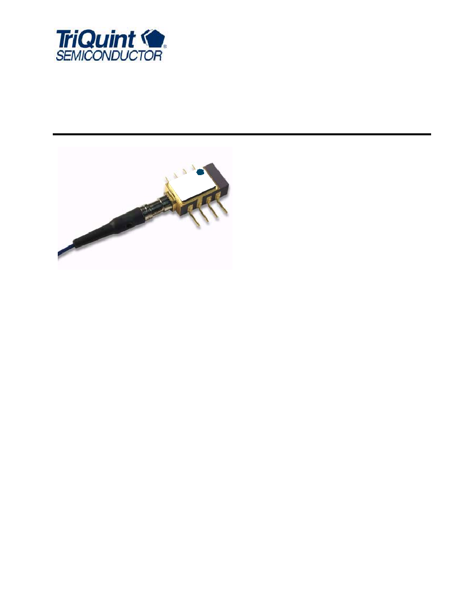
Description
The D572-type uncooled laser module consists of a
laser diode coupled to a single-mode fiber pigtail. The
device is available in a standard, 8-pin configuration
(see Figure 1 and/or Table 1) and is ideal for long-
reach (SONET) and other high-speed digital applica-
tions.
The module includes a narrow linewidth (<1 nm) DFB-
MQW single-mode laser and an InGaAs PIN photo-
diode back-facet monitor in a hermetically sealed pack-
age.
This package is optimized for a 25
input impedance
and allows for dc biasing through an internal bias tee.
A thermistor has been included for feedback to board-
level bias circuitry, if needed.
Æ
riQ
T
uin
t
SEM
ICO
NDU
CTO
R
D57
2-Ty
pe
DFB
Las
er M
odu
le

2
2
For additional information and latest specifications, see our website: www.triquint.com
D572-Type 1.5 µm Uncooled DFB Laser Module
Advance Data Sheet
for 2.5 Gb/s CWDM Applications
February 2003
Description
(continued)
The device characteristics listed in this document are
met at 2.0 mW output power. Higher- or lower-power
operation is possible. Under conditions of a fixed
photodiode current, the change in optical output is typi-
cally ±0.5 dB over an operating temperature range of
0 ∞C to +70 ∞C.
This device incorporates the new Laser 2000 manufac-
turing process from the Optoelectronic Products unit of
TriQuint Semiconductor. Laser 2000 is a low-cost plat-
form that targets high-volume manufacturing and
tighter product distributions on all optical subassem-
blies. This platform incorporates an advanced optical
design that is produced on one of the highly automated
production lines at the Opotelectronic manufacturing
facility. The Laser 2000 platform is qualified for the cen-
tral office and uncontrolled environments, and can be
used for applications requiring high performance and
low cost.
Table 1. Pin Descriptions
Pin Number
Connection
1
Thermistor
2
Thermistor, package GND
3
Laser dc bias cathode (≠) choke
4
Photodiode cathode
5
Photodiode anode
6
Laser diode anode (+)
7
Laser RF input cathode (≠) 25
8
Laser diode anode (+)
Figure 1. D572-Type Uncooled DFB Mini 8-Pin Laser Module Schematic, Top View
Absolute Maximum Ratings
Stresses in excess of the absolute maximum ratings can cause permanent damage to the device. These are abso-
lute stress ratings only. Functional operation of the device is not implied at these or any other conditions in excess
of those given in the operations sections of the data sheet. Exposure to absolute maximum ratings for extended pe-
riods can adversely affect device reliability.
* Rating varies with temperature.
Parameter
Symbol
Min
Max
Unit
Maximum Peak Laser Drive Current or
Maximum Fiber Power*
I
OP
P
MAX
--
--
150
10
mA
mW
Peak Reverse Laser Voltage:
Laser
Monitor
V
RL
V
RM
--
--
2
20
V
V
Monitor Forward Current
I
FD
--
2
mA
Operating Case Temperature Range
T
C
≠40
85
∞C
Storage Case Temperature Range
T
stg
≠40
85
∞C
Lead Soldering Temperature/Time
--
--
260/10
∞C/s
Relative Humidity (noncondensing)
RH
--
85
%
1-900.b
4
3
2
1
5
6
7
8

For additional information and latest specifications, see our website: www.triquint.com
3
Advance Data Sheet
D572-Type 1.5 µm Uncooled DFB Laser Module
February 2003
for 2.5 Gb/s CWDM Applications
Handling Precautions
CAUTION: This device is susceptible to damage as a result of electrostatic discharge (ESD). Take proper
precautions during both handling and testing. Follow guidelines such as JEDEC Publication
No. 108-A (Dec. 1988).
TriQuint Semiconductor employs a human-body model (HBM) for ESD-susceptibility testing and protection-design
evaluation. ESD voltage thresholds are dependent on the critical parameters used to define the model. A standard
HBM (resistance = 1.5 k
, capacitance = 100 pF) is widely used and can be used for comparison purposes.
Laser Safety Information
Class IIIb Laser Product
FDA/CDRH Class IIIb laser product. All versions are Class IIIb laser products per CDRH, 21 CFR 1040 Laser Safety
requirements. All versions are classified Class 3B laser products consistent with IEC
Æ
60825-1: 1993. This device
family has been classified with the FDA under accession number 8720010. Measurements were made to classify
the product per IEC 60825-1: 1993.
This product complies with 21 CFR 1040.10 and 1040.11.
8.3 µm single-mode pigtail or connector
Wavelength = 1470 nm, 1490 nm, 1510 nm 1530 nm, 1550 nm, 1570 nm, 1590 nm, or 1610 nm
Maximum power = 10 mW
Because of size constraints, laser safety labeling is not affixed to the module but attached to the outside of the
shipping carton.
Product is not shipped with power supply.
Caution: Use of controls, adjustments, and procedures other than those specified herein may result in hazardous
laser radiation exposure.
INVISIBLE LASER RADIATION EMITTED FROM END OF FIBER OR CONNECTOR
Avoid exposure to beam
Class IIIb Laser Product per CDRH, 21 CFR 1040
Max. Output: 10 mW
Wavelength: 1.5
µm
DANGER
INVISIBLE LASER RADIATION
IS EMITTED FROM THE END
OF FIBER OR CONNECTOR
Avoid direct exposure to beam
Do not view beam directly with
optical instruments

4
For additional information and latest specifications, see our website: www.triquint.com
D572-Type 1.5 µm Uncooled DFB Laser Module
Advance Data Sheet
for 2.5 Gb/s CWDM Applications
February 2003
Electrical/Optical Characteristics
1. BOL value; EOL = 80 mA.
2. The slope efficiency is used to calculate the modulation current for a desired output power. This modulation current plus the thresh-
old current comprise the total operating current for the device.
3. Corrected for electrical pulse fall time.
4. V
R
= reverse voltage.
Table 2. Electrical/Optical Characteristics (over operating temperature range unless otherwise noted)
Parameter
Symbol
Test Conditions
Min
Typ
Max
Unit
Operating Temperature
Range
T
--
0
--
70
∞C
Optical Output Power
P
F
CW, peak
--
2
--
mW
Threshold Current
I
TH
T = 25 ∞C
T = full range
5
2
11
--
15
60
mA
mA
Modulation Current
I
MOD
CW, P
F
= 2.0 mW, T = 25 ∞C
CW, I
MON
= constant,
T = full range
15
7.5
25
--
35
60
1
mA
mA
Slope Efficiency
2
SE
CW, P
F
= 2.0 mW, T = 25 ∞C
57
--
133
µ
W/mA
Center Wavelength
C
CW, P
F
= 2.0 mW, T = 25 ∞C
1470 nm codes
1490 nm codes
1510 nm codes
1530 nm codes
1550 nm codes
1570 nm codes
1590 nm codes
1610 nm codes
1467
1487
1507
1527
1547
1567
1587
1607
1470
1490
1510
1530
1550
1570
1590
1610
1473
1493
1513
1533
1553
1573
1593
1613
nm
Spectral Width (≠20 dB)
P
F
= 2.0 mW
--
--
1
nm
Side-mode Suppression
Ratio
SMSR
CW, P
F
= 2.0 mW
30
40
--
dB
Tracking Error
TE
I
MON
= constant, CW
--
--
1.5
dB
Spontaneous Emission
P
TH
I = (0.9) I
TH
--
--
100
µ
W
Rise/Fall Times
t
R
, t
F
10%--90% pulse
3
, T = 25 ∞C
--
0.125
0.175
ns
Optical Return Loss
ORL
CW
18
--
--
dB
Forward Voltage
V
F
At bias coil
--
1.0
1.6
V
Input Impedance
R
--
--
25
--
Monitor Current
I
MON
V
R4
= 5 V
100
--
1000
µ
A
Monitor Dark Current
I
D
V
R4
= 5 V
--
10
200
nA
Wavelength Tempera-
ture Coefficient
--
--
--
0.09
0.12
nm/∞C

For additional information and latest specifications, see our website: www.triquint.com
5
Advance Data Sheet
D572-Type 1.5 µm Uncooled DFB Laser Module
February 2003
for 2.5 Gb/s CWDM Applications
Qualification Information
The D572-type laser module is scheduled to complete the following qualification tests and meets the intent of
Telcordia Technologies TR-NWT-000468 for interoffice environments and TA-TSY-000983 for outside plant envi-
ronments.
Table 3. D572-Type Laser Module Qualification Test Plan
Qualification Test
Conditions
Sample Size
Reference
Mechanical Shock
500 G
11
MIL-STD-883
Method 2002
Vibration
20 g, 20 Hz--2,000 Hz
11
MIL-STD-883
Method 2007
Solderability
--
11
MIL-STD-883
Method 2007
Thermal Shock
Delta T = 100 ∞C
11
MIL-STD-883
Method 2003
Fiber Pull
1 kg; 3 times
11
Telcordia Technologies 983
Accelerated (Biased) Aging
85 ∞C, 5,000 hrs.
25
Telcordia Technologies 983
Section 5.18
High-temperature Storage
85 ∞C, 2,000 hrs.
11
Telcordia Technologies 983
Temperature Cycling
500 cycles
11
Telcordia Technologies 983
Section 5.20
Cyclic Moisture Resistance
10 cycles
11
Telcordia Technologies 983
Section 5.23
Damp Heat
40 ∞C, 95% RH,
1344 hrs.
11
MIL-STD-202
Method 103
Internal Moisture
<5,000 ppm water vapor
11
MIL-STD-883
Method 1018
Flammability
--
--
TR357
Section 4.4.2.5
ESD Threshold
--
6
Telcordia Technologies 983
Section 5.22
6
For additional information and latest specifications, see our website: www.triquint.com
D572-Type 1.5 µm Uncooled DFB Laser Module
Advance Data Sheet
for 2.5 Gb/s CWDM Applications
February 2003
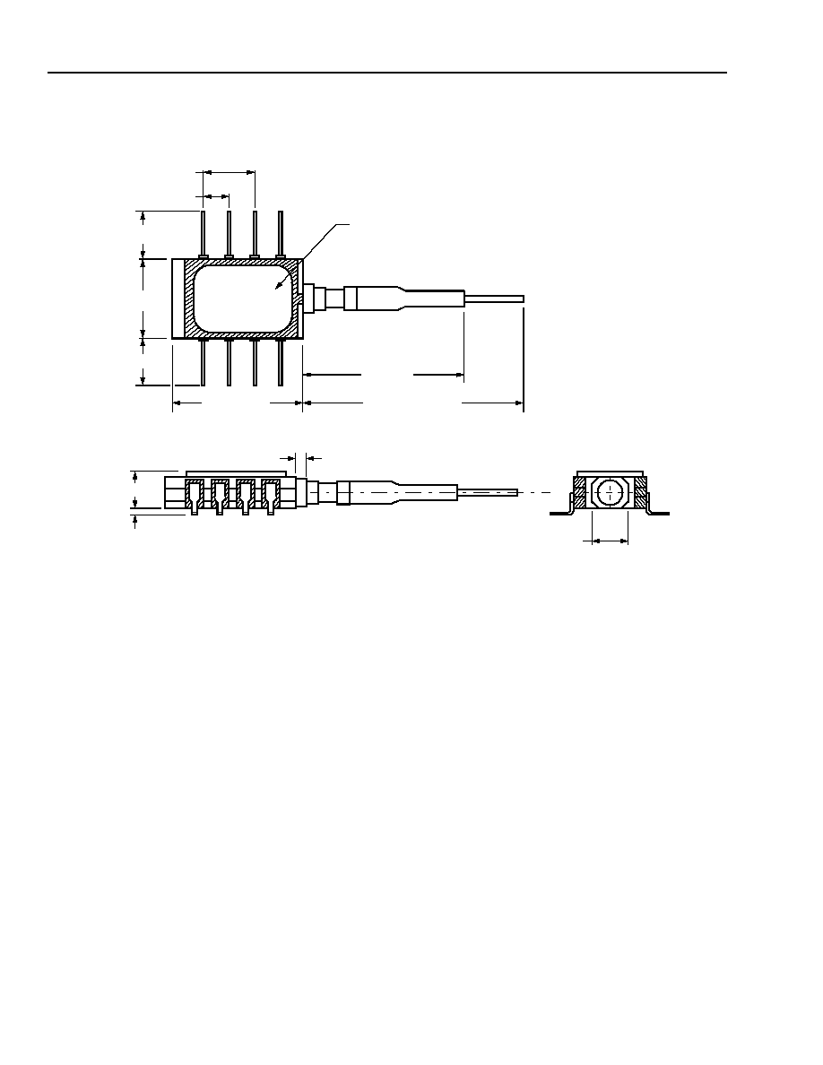
Outline Diagram
Dimensions are in inches and (millimeters).
TRADEMARK, CODE, LASER SERIAL NUMBER,
AND/OR DATE CODE IN APPROXIMATE AREA SHOWN
39.37 (1000) MIN
(PIGTAIL LENGTH)
0.52 (13.21)
0.300 (7.62)
0.100 (2.54)
0.17
(4.32)
0.045 (1.143)
0.02 (0.50)
0.20 (5.00)
0.169 (4.30)
0.29 (7.37)
0.169 (4.30)
1.06 (27.0)
MAX
Additional Information
For the latest specifications, additional product information, worldwide sales and distribution locations, and information about TriQuint:
Web: www.triquint.com
Tel: (503) 615-9000
E-mail: info_opto@tqs.com
Fax: (503) 615-8902
For technical questions and additional information on specific applications:
E-mail: info_opto@tqs.com
The information provided herein is believed to be reliable; TriQuint assumes no liability for inaccuracies or omissions. TriQuint assumes no responsibility for the use of this information, and all
such information shall be entirely at the user's own risk. Prices and specifications are subject to change without notice. No patent rights or licenses to any of the circuits described herein are
implied or granted to any third party.
TriQuint does not authorize or warranty any TriQuint product for use in life-support devices and/or systems.
Copyright © 2003 TriQuint Semiconductor Inc. All rights reserved.
DS02-357 Revision 1.1, February, 2003
D572-Type 1.5 µm Uncooled DFB Laser Module
Advance Data Sheet
for 2.5 Gb/s CWDM Applications
February 2003
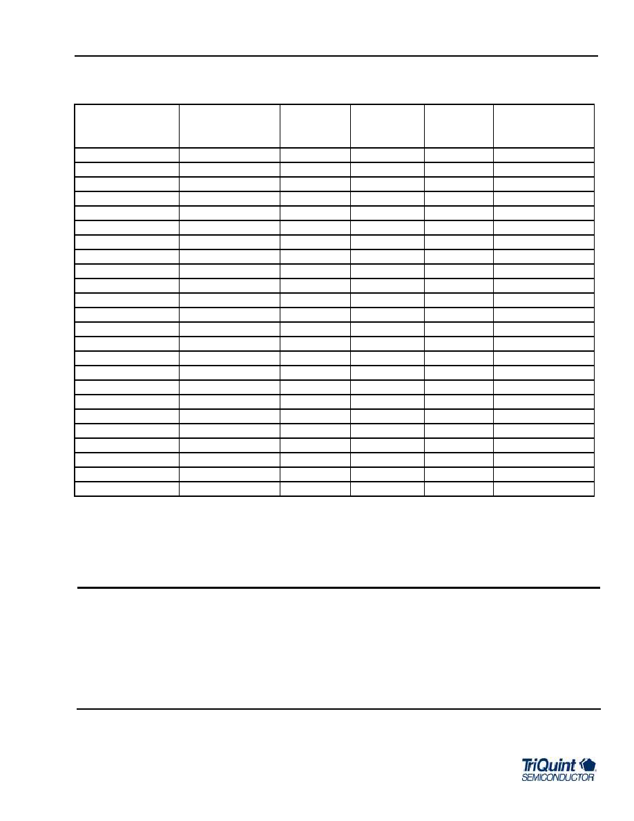
Ordering Information
*
Trailing S in code indicates the module contains an isolator.
Connectors will meet Telcordia Technologies GR-326-CORE.
Device Code*
Comcode
Pfiber
Center
Wavelength
Connector
Operating Case
Temperature
Range (∞C)
D572A25AS
TBD
2.0 mW
1470 nm
SC-PC
0 to +70
D572A25FS
TBD
2.0 mW
1470 nm
FC-PC
0 to +70
D572A25SS
TBD
2.0 mW
1470 nm
LC-PC
0 to +70
D572B25AS
TBD
2.0 mW
1490 nm
SC-PC
0 to +70
D572B25FS
TBD
2.0 mW
1490 nm
FC-PC
0 to +70
D572B25SS
TBD
2.0 mW
1490 nm
LC-PC
0 to +70
D572C25AS
700039354
2.0 mW
1510 nm
SC-PC
0 to +70
D572C25FS
700039355
2.0 mW
1510 nm
FC-PC
0 to +70
D572C25SS
700039358
2.0 mW
1510 nm
LC-PC
0 to +70
D572D25AS
700039359
2.0 mW
1530 nm
SC-PC
0 to +70
D572D25FS
700039360
2.0 mW
1530 nm
FC-PC
0 to +70
D572D25SS
700039361
2.0 mW
1530 nm
LC-PC
0 to +70
D572E25AS
700039364
2.0 mW
1550 nm
SC-PC
0 to +70
D572E25FS
700039368
2.0 mW
1550 nm
FC-PC
0 to +70
D572E25SS
700039369
2.0 mW
1550 nm
LC-PC
0 to +70
D572F25AS
700039370
2.0 mW
1570 nm
SC-PC
0 to +70
D572F25FS
700039374
2.0 mW
1570 nm
FC-PC
0 to +70
D572F25SS
700039379
2.0 mW
1570 nm
LC-PC
0 to +70
D572G25AS
TBD
2.0 mW
1590 nm
SC-PC
0 to +70
D572G25FS
TBD
2.0 mW
1590 nm
FC-PC
0 to +70
D572G25SS
TBD
2.0 mW
1590 nm
LC-PC
0 to +70
D572H25AS
TBD
2.0 mW
1610 nm
SC-PC
0 to +70
D572H25FS
TBD
2.0 mW
1610 nm
FC-PC
0 to +70
D572H25SS
TBD
2.0 mW
1610 nm
LC-PC
0 to +70
Telcordia Technologies is a trademark of Telcordia Technologies, Inc.
EIA is a registered trademark of The Electronic Industries Association.
IEC is a registered trademark of The International Electrotechnical Commission.