- 512 -
KBU801G THRU KBU807G
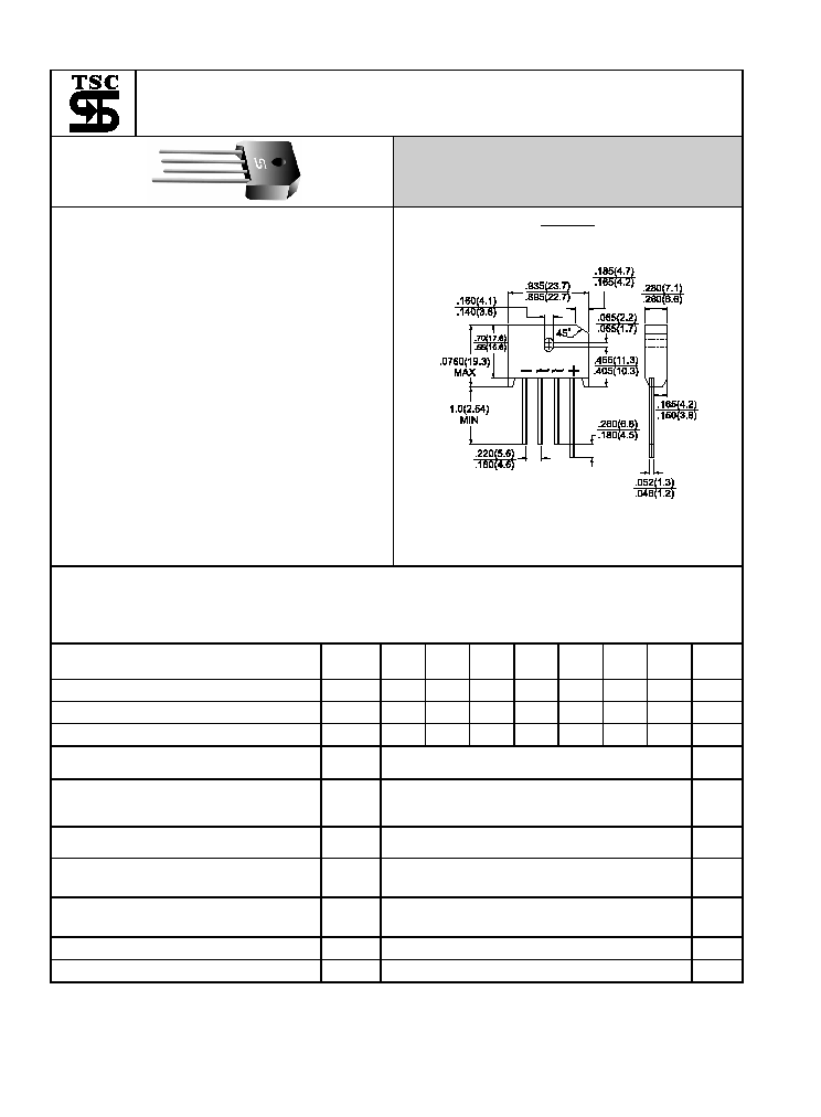
Single Phase 8.0 AMPS. Glass Passivated Bridge Rectifiers
Voltage Range
50 to 1000 Volts
Current
8.0 Amperes
Features
UL Recognized File # E-96005
Glass passivated junction
Ideal for printed circuit board
Reliable low cost construction
Plastic material has Underwriters
Laboratory Flammability Classification
94V-0
Surge overload rating to 200 amperes
peak
High temperature soldering guaranteed:
260
O
C / 10 seconds / .375", (9.5mm) lead
lengths.
Weight: 0. 3 ounce, 8.0 grams
Mounting torque: 5 in. lb. Max.
KBU
Dimensions in inches and (millimeters)
Maximum Ratings and Electrical Characteristics
Rating at 25
+
ambient temperature unless otherwise specified.
Single phase, half wave, 60 Hz, resistive or inductive load.
For capacitive load, derate current by 20%
Type Number
Symbol
KBU
801G
KBU
802G
KBU
803G
KBU
804G
KBU
805G
KBU
806G
KBU
807G
Units
Maximum Recurrent Peak Reverse Voltage
V
RRM
50
100
200
400
600
800 1000
V
Maximum RMS Voltage
V
RMS
35
70
140
280
420
560
700
V
Maximum DC Blocking Voltage
V
DC
50
100
200
400
600
800 1000
V
Maximum Average Forward Rectified Current
@T
A
= 65
+
I
(AV)
8.0
A
Peak Forward Surge Current, 8.3 ms Single
Half Sine-wave Superimposed on Rated
Load (JEDEC method )
I
FSM
200
A
Maximum Instantaneous Forward Voltage
@ 8.0A
V
F
1.0
V
Maximum DC Reverse Current @ T
A
=25
+
at Rated DC Blocking Voltage @ T
A
=125
+
I
R
5.0
500
uA
uA
Typical Thermal Resistance Per Leg
(Note 1)
(Note 2)
R
JA
R
JC
18.0
3.0
+
/W
Operating Temperature Range
T
J
-55 to +150
+
Storage Temperature Range
T
STG
-55 to + 150
+
Notes 1: Units Mounted In Free Air No Heat Sink On PCB 0.5x0.5 " (12x12mm) Copper Pads,
0.375"(9.5mm) Lead
Length.
2: Units Case Mounted On 3.2x3.2 x 0.12" Thick (8.2x8.2x0.3cm) AL. Plate Heat Sink.
REV.1 Oct.-2003

- 513-
RATINGS AND CHARACTERISTIC CURVES (KBU801G THRU KBU807G)
FIG.4- TYPICAL REVERSE CHARACTERISTICS
PER BRIDGE ELEMENT
INST
ANT
ANEOUS
REVERSE
CURRENT
.(
A
)
0
20
40
60
80
100
120
140
0.1
1
10
100
PERCENT OF RATED PEAK REVERSE VOLTAGE. (%)
TJ=125 C
0
TJ=25 C
0
FIG.3- TYPICAL INSTANTANEOUS FORWARD
CHARACTERISTICS PER BRIDGE ELEMENT
INST
ANT
ANEOUS
FOR
W
ARD
CURRENT
.
(A)
.7
.6
.8
1.0
.9
1.1
1.2
1.3
0.1
0.4
4.0
40
0.2
2.0
20
1.0
10
100
INSTANTANEOUS FORWARD VOLTAGE. (V)
FIG.1- MAXIMUM NON-REPETITIVE FORWARD SURGE
CURRENT PER BRIDGE ELEMENT
PEAK
FOR
W
ARD
SURGE
CURRENT
.
(A)
10
5
50
2
1
20
100
100
50
0
150
250
300
200
NUMBER OF CYCLES AT 60Hz
8.3ms Single Half Sine Wave
Tj=25 C
0
FIG.2- MAXIMUM FORWARD CURRENT DERATING
CURVE
A
VERAGE
FOR
W
ARD
CURRENT
.
(A)
50
0
100
150
0
2
4
6
10
8
AMBIENT TEMPERATURE. ( C)
o
MOUNTED ON 4X4 INCH
COPPER PC BOARD
0.5"(12.7mm) LEAD LENGTH