UTC PC1353
LINEAR INTEGRATED CIRCUIT
UTC
UNISONIC TECHNOLOGIES CO., LTD.
1
QW-R111-002,A
TV AUDIO PROCESSING CIRCUIT
DESCRIPTION
UTC PC1353 is designed for TV SIF signal amplification
and audio power amplification purpose. It includes SIF
amplifier, FM, frequency discriminator, DC volume control,
2.4W power amplifier and voltage regulator.
FEATURES
* Wide operating supply voltage,9V ~ 18V
When VCC=18V,RL=8
,Output is 2.4W(17"TV)
When VCC=12V,RL=8
,Output is 1.2W(12"TV)
* Linear volume control
* Low harmonic distortion
* Differential peak detector
* Attenuation circuit for noise suppression(Typical80dB)
DIP-14H
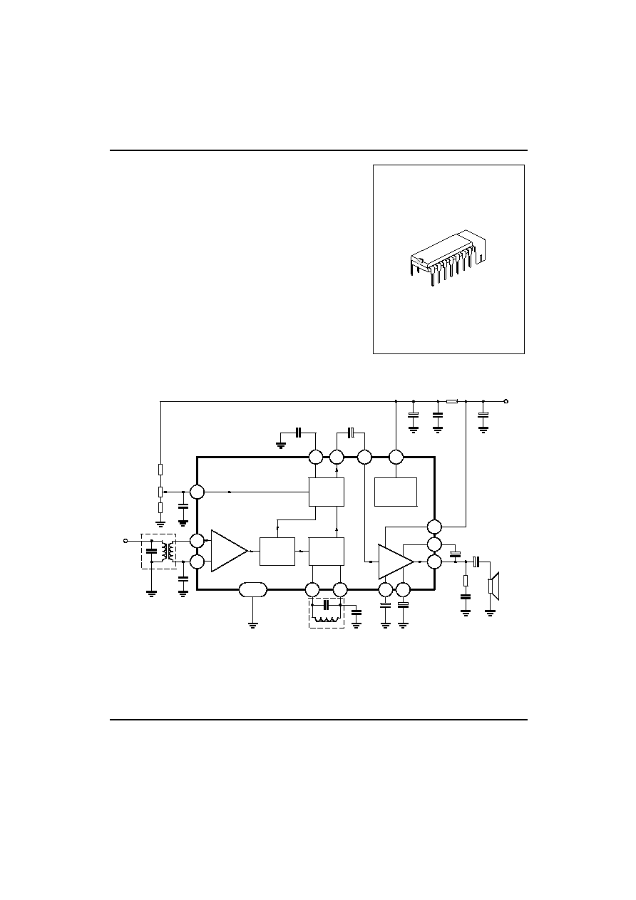
APPLICATION CIRCUIT
6
11
8
9
10
5
7
4
3
14
12
13
1
2
attenuator
IF voltage
regulation
IF amplifier
limiter
Mute
Frequency
discreminator
Power AMP
output
TAB
RB
220
µ
F
0.01
µ
F
100
µ
F
4.7
µ
F
0.015
µ
F
IF discreminator
output
IF power
input
Deweighting
Vcc
100
µ
F
330
µ
F
47
µ
F
470pF
22
100
µ
F
10pF
0.022
µ
F
0.1
µ
F
22k
VR
5k
270
Volume
control
Input
coil
FM
discreminator
coil
Decoupling
Bootstrap
Power for
audio output
Negative
Feedback
Fig 1

UTC PC1353
LINEAR INTEGRATED CIRCUIT
UTC
UNISONIC TECHNOLOGIES CO., LTD.
2
QW-R111-002,A
ABSOLUTE MAXIMUM RATING
(Ta=25
∞
C)
PARAMETER
SYMBOL
VALUE
UNIT
Input Voltage(pin 10)
V10
20
V
Input Current(pin10)
I10
1
A
Input Current(pin5)
I5
100
mA
Signal Voltage Input
VI
3
VP-P
Power Dissipation
PD1
0.8(Ta=75
∞
C)Free air
W
Power Dissipation
PD2
1
.4*
W
Operating Temperature
TOPR
-20 ~ +75
∞
C
Storage Temperature
TSTG
-40 ~ +150
∞
C
*Area of copper pattern on PCB 50 x 50(mm)2
ELECTRICAL CHARACTERISTICS
(Ta=25
∞
C)
1.TYPICAL CHARACTERISTICS
PARAMETER
SYMBOL
TEST CONDITIONS
VALUE
UNIT
Current for Pin 10
I10
THD2A=10%
200 ~ 210
mA
Current for Pin 10
I10
THD2B=10%
270 ~ 280
mA
Audio Output Power
POA
THD=3%
1.1
W
Audio Output Power
POB
VCC=18V,RB=330
,THD=3%
2.0
W
Bandwidth for Audio Stage
fS
-3dB
50 ~ 50K
HZ
2. IF AMPLIFIER
(V
CC
=12V,R
B
=100
,V
14>=
1.3V,f
O
=6.5MHZ,fm=400HZ,f=25KHZ,R
G
=50
)
PARAMETER
SYMBOL
TEST CONDITIONS
MIN
TYP
MAX
UNIT
Pin 5 Voltage
V5A
7.5
8.0
8.5
V
Pin5 Voltage
V5B
VCC=18V,RB=330
7.5
8.0
8.5
V
Pin10 Current
I10A
No input signal
14
19
24
mA
Pin10 Current
I10B
VCC=18V,RB=330
No input signal
16
28
35
mA
IF limiter Voltage
VLIM
VOAF(Vi=10mVrms)= -3dB
200
400
µ
Vrms
Discriminator Output
Voltage
VOAF
Vi=10mVrms
300
360
mVrms
Discriminator Distortion
THD1
Vi=10mVrms
0.7
%
AM rejection ratio
AMR
Modulation 30% fm=400HZ
Vi=10mVrms
-40
-50
dB
Maximum attenuation
VATT
V14=0V
-60
-80
dB

UTC PC1353
LINEAR INTEGRATED CIRCUIT
UTC
UNISONIC TECHNOLOGIES CO., LTD.
3
QW-R111-002,A
3.AUDIO POWER AMPLIFIER
(V
CC
=12V,R
B
=100
,R
L
=8
,f=400HZ,R
G
=600
)
PARAMETER
SYMBOL
TEST CONDITIONS
MIN
TYP
MAX
UNIT
Voltage Gain
GVAF
Vi=30mVrms
33
37
41
dB
Output Power
POA
THD=10%
0.9
1.2
W
Output Power
POB
VCC=18V,RB=330
THD=10%
2.0
2.4
W
Distortion
THD2A
PO=0.5W
0.6
2.0
%
Distortion
THD2B
VCC=18V,RB=330
PO=0.5W
0.5
2.0
%
Total Distortion(IF+Audio)
THD3
PO=0.5W
Vi=10mVrms
v
1.5
4.0
%
TEST CIRCUIT
3
7
4
11
14
6
5
2
10
8
1
12
13
TAB
9
V1
V14
V5
I5
VV
KF
I
10
KF
VV
VV
VV
Amp
Gain
Ê=
60dB
220
µ
F
330
µ
F
100
µ
F
0.01
µ
F
100
µ
F
220
µ
F
0.1
µ
F
10pF
0.022
µ
F
0.01
µ
F
47
µ
F
47
µ
F
0.015
µ
F
47
µ
F
47
µ
F
100
µ
F
600
R
L
=8
22k
5k
RG=50
Audio signal
f=400Hz
DCM
DVM
DVM
IF signal
f=6.5MHz
RB
S4
S3
S1
S2
RB : Vcc 12V:100
Vcc 18V:330
KF
VV AC voltmeter
Distortion
meter
UTC PC1353
Vcc
12V or 18V
Fig 2

UTC PC1353
LINEAR INTEGRATED CIRCUIT
UTC
UNISONIC TECHNOLOGIES CO., LTD.
4
QW-R111-002,A
TYPICAL PERFORMANCE CHARACTERISTICS
0
5
10
15
20
25
Power supply current
Icc (mA)
Power supply voltage
Vcc (V)
Power supply curve
0.5
1.0
1.5
2.0
2.5
0
2
6
4
8
10
12
14
16
18
20
0
2
6
4
8
10
12
14
16
18
20
f=1kHz
Vcc=12V
f=1kHz
Vcc=18V
Total distortion curve
Total distortion
THD2 (%)
Output power
Po(W)
0
100
200
300
400
500
-7
-6
-5
-4
-3
-2
-1
0
6
10
5
10
4
10
10
3
2
10
10
2
10
10
3
4
10
5
10
Vcc=12V
Vi=30mVrms
Vcc=12V
fo=6.5MHz
100%FM
30%AM
fm=400Hz
f=+25kHz
Vi=10mVrms
Frequency
(Hz)
Attenuation
ø
(dB)
Audio amplifier frequency response
curve
Detector output curve
Detector output voltage
π
Vout
(mVrms)
Input voltage
π
Vi
(
µ
Vrms)
0
50
100
150
0
1
2
3
Ambient temperature
Ta(
¢X
C)
Power
dissipation
PD(W)
Power dissipation curve
10
100
1000
0
1
2
3
4
5
V=18V
V=12V
f=1kHz
THD=10%
THD=10%
Audio power output curve
Input power Viaf(mVrms)
Output power Po(W)
PCB thickness t=1.5mm
Copper thickness
t=30
µ
m
50x50(mm)
2
Free air