X O
VF140
75 South Street, Hopkinton, MA 01748 800-982-5737 508-435-6831 Fax: 508-435-5289 www.valpeyfisher.com
54
Creating a Part Number
VF140
INPUT VOLTAGE
Code
Specification
L 3.3
Volt
5.0
Volt
(std.)
OUTPUT
Code
Specification
T
Tristate
Std.
FREQUENCY STABILITY
Code
Specification
S
±
20 ppm
A
±
25 ppm
B
±
50 ppm
±
100
ppm (std.)
C
±
500
ppm
DUTY CYCLE
Code
Specification
HH
±
2.5%
H
±
5%
±
10% (std.)
OPERATIONAL TEMP. RANGE
Code
Specification
0
∞
C to +70
∞
C (std.)
1 -40
∞
C to +85
∞
C
2 -55
∞
C to +125
∞
C*
*Not always available
FREQ.
Example: VF140BL-1-1.8432MHz: Frequency Stability
±
50ppm, Duty Cycle
±
10%, Input Voltage 3.3 Volt
±
5%, Operating Temperature -40
∞
C to +85
∞
C,
Output Non-Tristate, Lead Configuration Straight, Frequency 1.8432MHz.
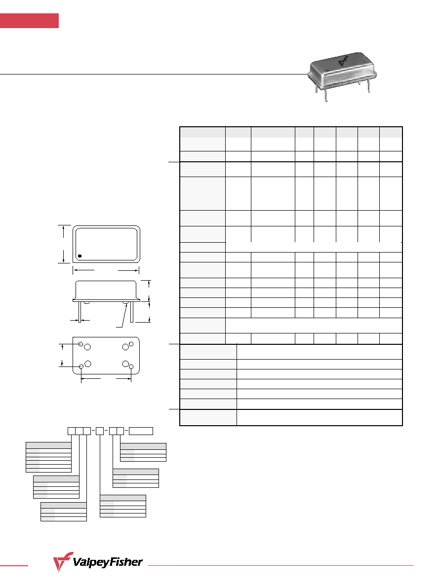
LEAD CONFIGURATION
Code
Specification
G
Gull Wing
Through hole
0.800"
(20,32mm)
0.300"
(7,62mm)
#1
#7
#8
#14
0.600"
(15,24mm)
GLASS STANDOFFS
0.497"
(12,62mm)
0.254"
(6,45mm)
VF140
1.8432MHZ
BO1H
0.250"
(6,35mm)
¯0.0180"
±
0.002"
(0,460mm
±
0,051mm)
VF140
HCMOS/TTL Compatible
Clock Oscillators
F E AT U R E S
∑
Tristate Output Available
∑
Low Cost
∑
Industrial and Military
Temperature Available
∑
Wide Frequency Range
∑
Very Low Phase Jitter
Parameter
Symb
Condition
Min
Typ
Max
Unit
Note
Input Break
Vcc
≠0.5
7.0
V
Down Voltage
Storage Temp.
Ts
≠55
+125
∞C
Frequency F
0.2
130
MHz
Range
Frequency
F/F
Overall conditions
±100
ppm
1
Stability
including:
calibration, temp.,
aging 10 yrs,
shock, vibration
Input Voltage
Vcc
4.75
5.00
5.25
V
Std.
3.15
3.30
3.45
LV Opt.
Input Current
Icc
F = 50MHz
40
mA
2
15pF, load Vcc 5V
Load
Duty Cycle
@1.4V
40
50
60
%
3
Rise/Fall Time
Tr/Tf
0.4V to 2.4V
1.5
ns
20% to 80%
4.0
Logic "1" Level
Voh
Max Load
0.9Vcc
V
Logic "0" Level
Vol
Max Load
0.1Vcc
V
Start≠up Time
Ts
2
10
ms
Phase Jitter
1
1
ps
fj>1KHz
Tristate
Function
Enable Time
100
ns
Operating
Temperature Range
0∞C to +70∞C (≠40∞C to +85∞C, ≠55∞C to +125∞C available)
Mechanical Shock
Per MIL≠STD≠202, Method 213, Cond. E
Thermal Shock
Per MIL≠STD≠883, Method 1011, Cond. A
Vibration
Per MIL≠STD≠883, Method 2007, Cond. A
Soldering Conditions
260∞C, for 10s, Max.
Hermetic Seal
Leak rate less than 5 x 10
≠8
atm.cc/s of helium
Pin Out
Pin #1≠Tristate Control or N/C
Pin #2≠Ground, Case
Pin #3≠Output
Pin #4≠Vcc
10 TTL gates or 50pF Max.
Absolute
Max. Ratings
Electrical
Environmental and Mechanical
Electrical
Connections
Notes:
1. Standard frequency stability (±20, ±25, ±50, others available).
2. Current is load and frequency dependent.
3. Tighter duty cycles available.
All specifications are subject to change without notice.
All dimensions are typical unless otherwise specified.
Input HIGH (>2.5V) or floating:
ACTIVE
Input LOW (<0.5V):
INFINITE IMPEDANCE