AGP15 Series
Vishay Semiconductors
formerly General Semiconductor
Document Number 88535
www.vishay.com
08-Jul-02
1
Miniature Glass Passivated Junction
Plastic Controlled Avalanche Rectifiers
Reverse Voltage
400 to 800V
Forward Current 1.5A
Patented*
Maximum Ratings & Thermal Characteristics
Ratings at 25∞C ambient temperature unless otherwise specified.
Parameter
Symbol
AGP15-400 AGP15-600 AGP15-800
Unit
Maximum Recurrent Peak Reverse Voltage
V
RRM
400
600
800
V
Maximum RMS voltage
V
RMS
280
420
560
V
Maximum DC blocking voltage
V
DC
400
600
800
V
Maximum Peak Power Dissipation in the
Avalanch Region 20
µ
s Pulse
P
RM
500
W
Max. Average Forward Rectified Current 0.375" (9.5mm)
I
AV
1.5
A
Lead Lengths at T
A
= 55∞C
Peak forward surge current 8.3ms single half sine-wave
I
FSM
50
A
superimposed on rated load (JEDEC Method)
Maximum full load reverse current, full cycle average
0.375" (9.5mm) lead length at T
A
= 55∞C
I
R(AV)
100
µ
A
Typical thermal resistance
(Note 1)
R
JA
25
∞C/W
Operating and storage temperature range
T
J
, T
STG
≠65 to +175
∞C
Electrical Characteristics
Ratings at 25∞C ambient temperature unless otherwise specified.
Minimum Avalanche Breakdown Voltage at 100
µ
A
V
BR
450
675
880
V
Maximum Avalanche Breakdown Voltage at 100
µ
A
V
BR
750
1000
1200
V
Maximum instantaneous forward voltage at 1.5A
V
F
1.1
V
Maximum reverse current at rated DC blocking voltage
I
R
5.0
µ
A
Typical reverse recovery time I
F
=0.5A, I
R
=1.0A, I
rr
=0.25A
t
rr
2.0
µ
s
Typical junction capacitance at 4.0V, 1MHz
C
J
15
pF
Note: (1) Thermal resistance from junction to ambient at 0.375" (9.5mm) lead length, P.C. Board mounted
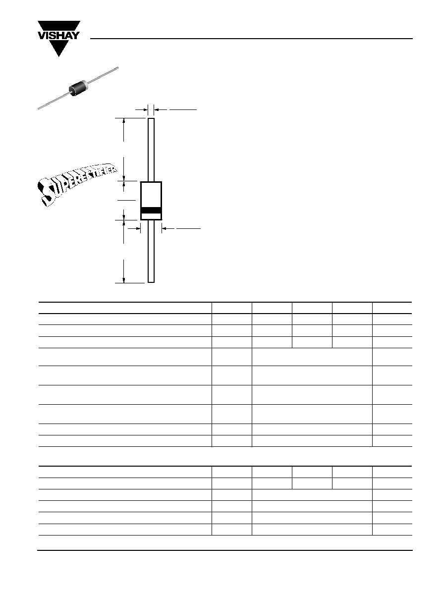
DO-204AC
(DO-15)
Features
∑ Plastic package has Underwriters Laboratory
Flammability Classification 94V-0
∑ High temp. metallurgically bonded constructed rectifiers
∑ Controlled Avalanche characteristic combined with the
ability to dissipate reverse power
∑ Glass passivated cavity-free junction in DO-15 package
∑ 1.5 Ampere operation at T
A
=55∞C with no thermal runaway
∑ Typical I
R
less than 0.1
µ
A
∑ Capable of meeting environmental standards of MIL-S-19500
∑ High temperature soldering guaranteed: 350∞C/10 seconds,
0.375" (9.5mm) lead length, 5 lbs. (2.3kg) tension
Mechanical Data
Case: Molded plastic over glass
Terminals: Plated axial leads, solderable per
MIL-STD-202, Method 208
Polarity: Color band denotes cathode end
Mounting Position: Any
Weight: 0.0154 oz., 0.4 g
0.034 (0.86)
0.028 (0.71)
Dia.
0.140 (3.6)
0.104 (2.6)
Dia.
0.230 (5.8)
0.300 (7.6)
1.0 (25.4)
min.
1.0 (25.4)
min.
Æ
*
Glass-plastic encapsulation
technique is covered by
Patent No. 3,996,602 of 1976;
brazed-lead assembly by
Patent No. 3,930,306 of 1976
and glass composition by
Patent No. 3,752,701 of 1973
Dimensions in inches
and (millimeters)

AGP15 Series
Vishay Semiconductors
formerly General Semiconductor
www.vishay.com
Document Number 88535
2
08-Jul-02
Ratings and
Characteristic Curves
(T
A
= 25∞C unless otherwise noted)
0.1
Instantaneous F
orw
ard Current (A)
Instantaneous Forward Voltage (V)
0
0.75
1.0
1.5
25
50
75
100
125
150
175
Fig. 1 ≠ Maximum Forward Current
Derating Curve
Fig. 2 ≠ Typical Instantaneous
Forward Characteristics
A
v
er
age F
orw
ard Rectified Current (A)
Ambient Temperature (
∞
C)
Number of Cycles at 60H
Z
Fig. 3 ≠ Maximum Non-Repetitive Peak
Forward Surge Current
0
20
60
40
100
80
Fig. 4 ≠ Typical Reverse Leakage
Characteristics
Instantaneous Re
v
erse Leakage Current
(
µ
A)
Percent of Rated Peak Reverse Voltage (%)
0.5
0.25
1.25
Single Phase Half Wave
60H
Z
Resistive or Inductive Load
0.375" (9.5mm) Lead Length
10
100
1
P
eak F
orw
ard Surge Current (A)
T
J
= 125
∞
C
T
J
= 25
∞
C
Pulse Duration (
µ
s)
P
eak Re
v
erse A
v
alanche P
o
w
er (W)
10
100
1,000
10,000
10
1
10
100
0.01
0.1
10
1
T
J
= 75
∞
C
Fig. 5 ≠ Maximum Non-Repetitive
Reverse Avalanche Power Dissipation
10
.6
.4
.8
1.0
1.2
1.4
1.6
0.01
1.0
T
J
= 25
∞
C
Pulse Width = 300
µ
s
2% Duty Cycle
T
A
= 55
∞
C
8.3ms Single Half Sine-Wave
(JEDEC Method)
100
1,000
T
J
= 25
∞
C