 | –≠–ª–µ–∫—Ç—Ä–æ–Ω–Ω—ã–π –∫–æ–º–ø–æ–Ω–µ–Ω—Ç: BFP181T | –°–∫–∞—á–∞—Ç—å:  PDF PDF  ZIP ZIP |
BFP181T/BFP181TW/BFP181TRW
Vishay Telefunken
www.vishay.de
∑
FaxBack +1-408-970-5600
Rev. 3, 20-Jan-99
1 (6)
Document Number 85012
Silicon NPN Planar RF Transistor
Electrostatic sensitive device.
Observe precautions for handling.
Applications
For low noise and high gain broadband amplifiers at
collector currents from 0.5 mA to 12 mA.
Features
D
Low noise figure
D
High power gain
2
1
3
13 653
4
13 566
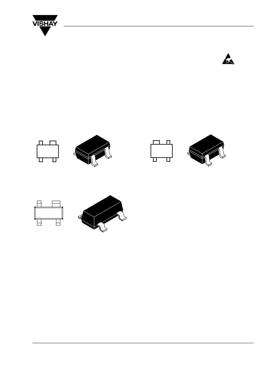
BFP181TW Marking: W18
Plastic case (SOT 343)
1 = Collector, 2 = Emitter, 3 = Base, 4 = Emitter
2
1
3
4
13 566
13 654
BFP181TRW Marking: WSF
Plastic case (SOT 343R)
1 = Collector, 2 = Emitter, 3 = Base, 4 = Emitter
13 579
2
1
4
3
94 9279
BFP181T Marking: 18
Plastic case (SOT 143)
1 = Collector, 2 = Emitter, 3 = Base, 4 = Emitter

BFP181T/BFP181TW/BFP181TRW
Vishay Telefunken
www.vishay.de
∑
FaxBack +1-408-970-5600
Rev. 3, 20-Jan-99
2 (6)
Document Number 85012
Absolute Maximum Ratings
T
amb
= 25
_
C, unless otherwise specified
Parameter
Test Conditions
Symbol
Value
Unit
Collector-base voltage
V
CBO
15
V
Collector-emitter voltage
V
CEO
10
V
Emitter-base voltage
V
EBO
2
V
Collector current
I
C
20
mA
Total power dissipation
T
amb
78
∞
C
P
tot
160
mW
Junction temperature
T
j
150
∞
C
Storage temperature range
T
stg
≠65 to +150
∞
C
Maximum Thermal Resistance
T
amb
= 25
_
C, unless otherwise specified
Parameter
Test Conditions
Symbol
Value
Unit
Junction ambient
on glass fibre printed board (25 x 20 x 1.5) mm
3
plated with 35
m
m Cu
R
thJA
450
K/W

BFP181T/BFP181TW/BFP181TRW
Vishay Telefunken
www.vishay.de
∑
FaxBack +1-408-970-5600
Rev. 3, 20-Jan-99
3 (6)
Document Number 85012
Electrical DC Characteristics
T
amb
= 25
_
C, unless otherwise specified
Parameter
Test Conditions
Symbol
Min
Typ
Max Unit
Collector cut-off current
V
CE
= 15 V, V
BE
= 0
I
CES
100
m
A
Collector-base cut-off current
V
CB
= 10 V, I
E
= 0
I
CBO
100
nA
Emitter-base cut-off current
V
EB
= 1 V, I
C
= 0
I
EBO
1
m
A
Collector-emitter breakdown voltage I
C
= 1 mA, I
B
= 0
V
(BR)CEO
10
V
Collector-emitter saturation voltage
I
C
= 15 mA, I
B
=1.5 mA
V
CEsat
0.1
0.4
V
DC forward current transfer ratio
V
CE
= 6 V, I
C
= 5 mA
h
FE
50
100
150
V
CE
= 6 V, I
C
= 10 mA
h
FE
100
Electrical AC Characteristics
T
amb
= 25
_
C, unless otherwise specified
Parameter
Test Conditions
Symbol
Min
Typ
Max
Unit
Transition frequency
V
CE
= 3 V, I
C
= 6 mA, f = 500 MHz
f
T
6.8
GHz
q
y
V
CE
= 8 V, I
C
= 10 mA, f = 500 MHz
f
T
8.0
GHz
Collector-base capacitance
V
CB
= 10 V, f = 1 MHz
C
cb
0.3
pF
Collector-emitter capacitance
V
CE
= 10 V, f = 1 MHz
C
ce
0.2
pF
Emitter-base capacitance
V
EB
= 0.5 V, f = 1 MHz
C
eb
0.45
pF
Noise figure
V
CE
= 5 V, I
C
= 3 mA, Z
S
= Z
Sopt
,
f = 900 MHz
F
1.5
dB
V
CE
= 5 V, I
C
= 3 mA, Z
S
= Z
Sopt
,
f = 1.75 GHz
F
2.2
dB
Power gain
V
CE
= 8 V, I
C
= 8 mA, Z
S
= 50
W
,
Z
L
= Z
Lopt
, f = 900 MHz
G
pe
16.5
dB
V
CE
= 8 V, I
C
= 8 mA, Z
S
= 50
W
,
Z
L
= Z
Lopt
, f = 1.75 GHz
G
pe
13.5
dB
Transducer gain
V
CE
= 8 V, I
C
= 8 mA, Z
0
= 50
W
,
f = 900 MHz
S
21e
2
16
dB
BFP181T/BFP181TW/BFP181TRW
Vishay Telefunken
www.vishay.de
∑
FaxBack +1-408-970-5600
Rev. 3, 20-Jan-99
4 (6)
Document Number 85012
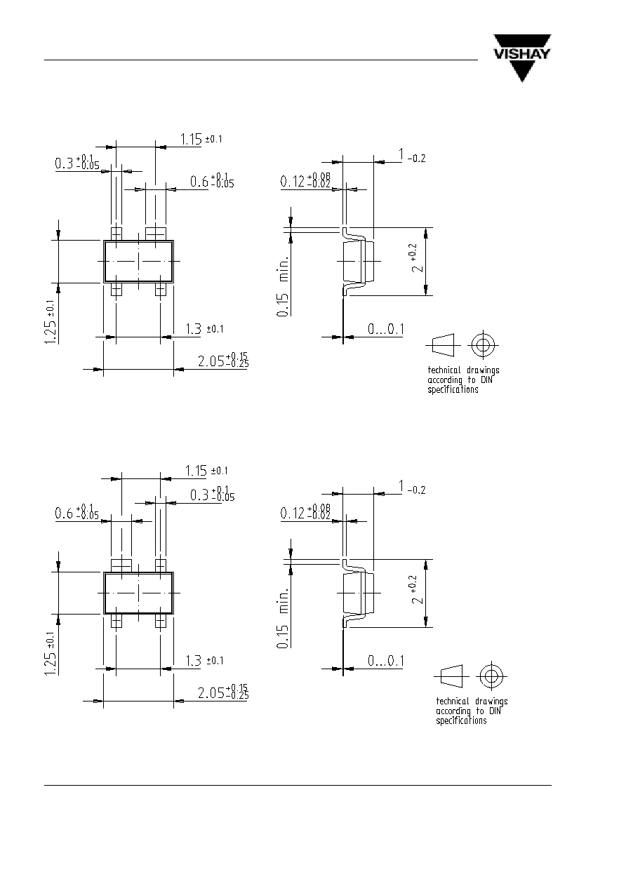
Dimensions of BFP181TW in mm
96 12237
Dimensions of BFP181TRW in mm
96 12238

BFP181T/BFP181TW/BFP181TRW
Vishay Telefunken
www.vishay.de
∑
FaxBack +1-408-970-5600
Rev. 3, 20-Jan-99
5 (6)
Document Number 85012
Dimensions of BFP181T in mm
96 12240