
GSIB2520 thru GSIB2580
Vishay Semiconductors
formerly General Semiconductor
Document Number 88646
www.vishay.com
1-Dec-03
1
New Product
Single-Phase Single In-Line
Bridge Rectifiers
Reverse Voltage 200 to 800V
Forward Current 25A
2.5
±
0.2
2.2
±
0.2
1
±
0.1
10
±
0.2
7.5
±
0.2
4
±
0.2
5
20
±
0.3
17
.
5
±
0.5
11
±
0.2
2.7
±
0.2
3.5
±
0.2
3.2
±
0.2
0.7
±
0.1
4.6
±
0.2
3.6
±
0.2
+
7.5
±
0.2
30
±
0.3
Case Style GSIB-5S
Dimensions in millimeters
Maximum Ratings & Thermal Characteristics
Ratings at 25∞C ambient temperature unless otherwise specified.
Parameter
Symbol
GSIB2520 GSIB2540 GSIB2560 GSIB2580
Unit
Maximum repetitive peak reverse voltage
V
RRM
200
400
600
800
V
Maximum RMS voltage
V
RMS
140
280
420
560
V
Maximum DC blocking voltage
V
DC
200
400
600
800
V
Maximum average forward rectified
T
C
= 98∞C
25
(1)
output current at
T
A
= 25∞C
I
F(AV)
3.5
(2)
A
Peak forward surge current single sine-wave
superimposed on rated load (JEDEC Method)
I
FSM
350
A
Rating for fusing (t < 8.3ms)
I
2
t
500
A
2
sec
Maximum thermal resistance per leg
R
JA
22
(2)
R
JC
1.0
(1)
∞C/W
Operating junction and storage temperature range
T
J
, T
STG
≠55 to +150
∞C
Electrical Characteristics
Ratings at 25∞C ambient temperature unless otherwise specified.
Parameter
Symbol
GSIB2520 GSIB2540 GSIB2560 GSIB2580
Unit
Maximum instantaneous forward voltage drop
per leg at 12.5A
V
F
1.00
V
Maximum DC reverse current at
T
A
= 25∞C
10
rated DC blocking voltage per leg
T
A
= 125∞C
I
R
350
µA
Notes: (1) Unit case mounted on Al plate heatsink
(2) Units mounted on P.C.B. without heatsink
(3) Recommended mounting position is to bolt down on heatsink with silicone
thermal compound for maximum heat transfer with #6 screw
Features
∑ Plastic package has Underwriters Laboratory
Flammability Classification 94V-0
∑ This series is UL listed under the Recognized
Component Index, file number E54214.
∑ High case dielectric strength of 2500 V
RMS
∑ Ideal for printed circuit boards
∑ Glass passivated chip junction
∑ High surge current capability
Mechanical Data
Case: GSIB-5S Molded plastic body
Terminals: Plated leads solderable per MIL-STD-750,
Method 2026
High temperature soldering guaranteed:
260∞C/10 seconds, 0.375 (9.5mm) lead length,
5lbs. (2.3kg) tension
Mounting Position: Any
(Note 3)
Mounting Torque: 8 in-lbs max.
Weight: 0.26 oz., 7.0 g
GSIB2520 thru GSIB2580
Vishay Semiconductors
formerly General Semiconductor
www.vishay.com
Document Number 88646
2
1-Dec-03
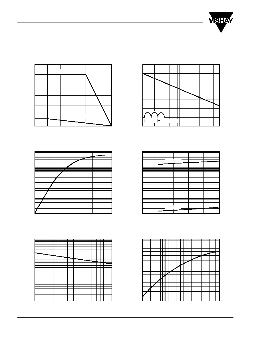
Ratings and
Characteristic Curves
(T
A
= 25∞C unless otherwise noted)
0
50
100
150
200
300
350
400
1
100
Fig. 2 ≠ Maximum Non-Repetitive Peak
Forward Surge Current Per Leg
Peak Forward Surge Current (A)
Number of Cycles at 60 H
Z
0
15
20
0
25
50
75
100
125
150
A
verage Forward Output Current (A)
0.60
1.00
1.20
1.40
0.80
Instantaneous Forward Voltage (V)
Fig. 3 ≠ Typical Forward Characteristics
Per Leg
0
20
60
40
100
80
Fig. 4 ≠ Typical Reverse Characteristics
Per Leg
Instantaneous Reverse Current (
µ
A)
Percent of Rated Peak Reverse Voltage (%)
10
5
Heat-Sink Mounting, T
C
P.C.B. Mounting,
0.01
0.1
10
1
100
Instantaneous Forward Current (A)
T
A
= 125
∞C
T
A
= 25
∞C
Fig. 5 ≠ Typical Junction Capacitance
Per Leg
Reverse Voltage (V)
Junction Capacitance (pF)
1
10
100
1000
1
10
100
Fig. 6 ≠ Typical Transient Thermal
Impedance
t, Heating Time (sec)
1.0 Cycle
0.1
1
100
10
1000
10
1
0.1
0.1
1
10
25
30
Temperature (
∞C)
10
Fig. 1 ≠ Derating Curve Output
Rectified Current
T
r
ansient
Thermal Impedance (
∞
C/W)
0.01