 | –≠–ª–µ–∫—Ç—Ä–æ–Ω–Ω—ã–π –∫–æ–º–ø–æ–Ω–µ–Ω—Ç: SML4749 | –°–∫–∞—á–∞—Ç—å:  PDF PDF  ZIP ZIP |
VISHAY
SML4728 to SML4764A
Document Number 85782
Rev. 1.5, 03-Mar-04
Vishay Semiconductors
www.vishay.com
1
15811
Surface Mount Zener Diodes
Features
∑ Plastic package has Underwriters Laboratory
Flammability Classification 94 V-0
∑ For surface mounted applications
∑ Low Zener impedance
∑ Low regulation factor
∑ High temperature soldering guaranteed:
260 ∞C/10 seconds at terminals
∑ Standard voltage tolerance is 10 %, Suffix A ± 5 %.
Mechanical Data
Case: JEDEC DO-214AC molded plastic over
passivated junction
Terminals: Solder plated, solderable per
MIL-STD- 750, Method 2026
Polarity: Color band denotes positive end (cathode)
Mounting Position: Any
Weight: 0.002 ounce, 64 mg
Packaging Codes - Options (Antistatic):
SML4728 - SML4737A:
11T - 1.8 k per 7" plastic reel (12mm tape), 36 k/car-
ton
5AT - 7.5 k per 13" plastic reel (12mm tape), 75 k/car-
ton
SML4738 - SML4764A:
61 - 1.8 k per 7" plastic reel (12mm tape), 36 k/carton
5A - 7.5 k per 13" plastic reel (12mm tape), 75 k/car-
ton
Absolute Maximum Ratings
T
amb
= 25 ∞C, unless otherwise specified
Thermal Characteristics
T
amb
= 25 ∞C, unless otherwise specified
Parameter
Test condition
Symbol
Value
Unit
Power dissipation
T
L
= 75 ∞C
P
tot
1.0
W
Parameter
Test condition
Symbol
Value
Unit
Maximum junction temperature
T
j
150
∞C
Storage temperature range
T
S
- 65 to + 150
∞C
www.vishay.com
2
Document Number 85782
Rev. 1.5, 03-Mar-04
VISHAY
SML4728 to SML4764A
Vishay Semiconductors
Electrical Characteristics
1)
Based on dc- measurement at thermal equilibrium
2)
Surge current is a non-repetitive, 8.3 ms pulse width square wave or equivalent sine-wave superimposed on I
ZT
per JEDEC Method
Partnumber
Device
Marking
Code
Nominal
Zener
Voltage
Test
Current
Maximum Dynamic
ImpedanceResistance
Maximum DC Reverse
Leakage Current
Maximum
Surge
Current
V
Z
1)
@ I
ZT
I
ZT
Z
ZT
@ I
ZT
Z
ZK
@ I
ZK
I
ZK
I
R
V
R
I
RM
2)
V
mA
mA
µA
V
mApk
SML4728
3P3
3.3
76
10
400
1
100
1
1380
SML4729
3P6
3.6
69
10
400
1
100
1
1260
SML4730
3P9
3.9
64
9
400
1
50
1
1190
SML4731
4P3
4.3
58
9
400
1
10
1
1070
SML4732
4P7
4.7
53
8
500
1
10
1
970
SML4733
5P1
5.1
49
7
550
1
10
1
890
SML4734
5P6
5.6
45
5
600
1
10
2
810
SML4735
6P2
6.2
41
2
700
1
10
3
730
SML4736
6P8
6.8
37
3.5
700
1
10
4
660
SML4737
7P5
7.5
34
4
700
0.5
10
5
605
SML4738
8P2
8.2
31
4.5
700
0.5
10
6
550
SML4739
9P1
9.1
28
5
700
0.5
10
7
500
SML4740
10
10
25
7
700
0.25
10
7.6
454
SML4741
11
11
23
8
700
0.25
5
8.4
414
SML4742
12
12
21
9
700
0.25
5
9.1
380
SML4743
13
13
19
10
700
0.25
5
9.9
344
SML4744
15
15
17
14
700
0.25
5
11.4
305
SML4745
16
16
15.5
16
700
0.25
5
12.2
285
SML4746
18
18
14
20
750
0.25
5
13.7
250
SML4747
20
20
12.5
22
750
0.25
5
15.2
225
SML4748
22
22
11.5
23
750
0.25
5
16.7
205
SML4749
24
24
10.5
25
750
0.25
5
18.2
190
SML4750
27
27
9.5
35
750
0.25
5
20.6
170
SML4751
30
30
8.5
40
1000
0.25
5
22.8
150
SML4752
33
33
7.5
45
1000
0.25
5
25.1
135
SML4753
36
36
7
50
1000
0.25
5
27.4
125
SML4754
39
39
6.5
60
1000
0.25
5
29.7
115
SML4755
43
43
6
70
1500
0.25
5
32.7
110
SML4756
47
47
5.5
80
1500
0.25
5
35.8
95
SML4757
51
51
5
95
1500
0.25
5
38.8
90
SML4758
56
56
4.5
110
2000
0.25
5
42.6
80
SML4759
62
62
4
125
2000
0.25
5
47.1
70
SML4760
68
68
3.7
150
2000
0.25
5
51.7
65
SML4761
75
75
3.3
175
2000
0.25
5
56
60
SML4762
82
82
3
200
3000
0.25
5
62.2
55
SML4763
91
91
2.8
250
3000
0.25
5
69.2
50
SML4764
100
100
2.5
350
3000
0.25
5
76
45
VISHAY
SML4728 to SML4764A
Document Number 85782
Rev. 1.5, 03-Mar-04
Vishay Semiconductors
www.vishay.com
3
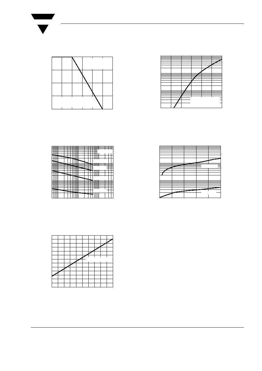
Typical Characteristics
(T
amb
= 25
∞C unless otherwise specified)
Fig. 1 Maximum Continuous Power Dissipation
Fig. 2 Typical Zener Impedance
Fig. 3 Typical Temperature Coefficients
25
50
75
100
125
150
175
0
0.25
0.5
0.75
1.0
Terminals Temperature (
∞C)
P
M(AV)
,
Average
Power
Dissipation
(W)
60 Hz
Resistive or
Inductive Load
P.C.B. Mounted on
0.31 x 0.31 x 0.08" (8 x 8 x 2mm)
copper areas pads
17923
0.5
10
100
500
1
10
100
1,000
IZT, Zener Test Current (mA)
Z Z
,
D
ynamic
Zener
Impedance
(
)
TJ = 25∞C
VZ = 91V
VZ = 56V
VZ = 30V
VZ = 6.2V
17925
0
10 20 30 40 50 60 70 80 90 100
0
10
30
50
70
90
110
VZ, Zener Voltage (V)
V
Z
,
Temperature
Coefficient
(mV/
∞
C)
Tested at rated IZT
17927
Fig. 4 Typical Instantaneous Forward Characteristics for
SML4763
Fig. 5 Typical Reverse Characteristics
0.4
0.6
0.8
1.0
1.2
1.4
1.6
0.01
0.1
1
10
Instantaneous Forward Voltage (V)
Instantaneous
Forward
Current
(A)
Pulse width = 300µs
1% Duty Cycle
TJ = 25∞C
17924
0
20
40
60
80
100
0.01
0.1
1
10
Percent of Rated Zener Voltage (%)
Instantaneous
Reverse
Current
(
µ
A)
TJ = 25∞C
TJ = 100∞C
17926
www.vishay.com
4
Document Number 85782
Rev. 1.5, 03-Mar-04
VISHAY
SML4728 to SML4764A
Vishay Semiconductors
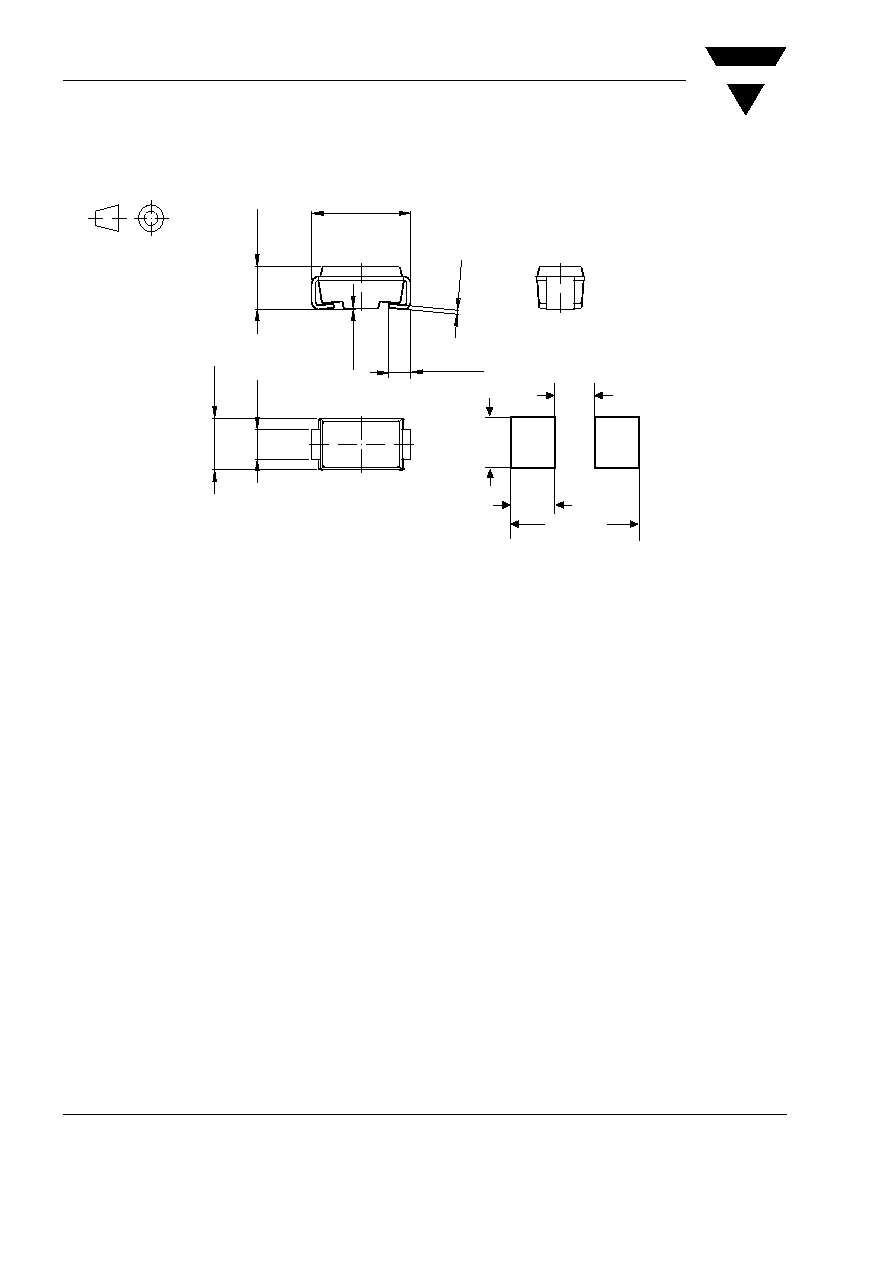
Package Dimensions in mm (Inches)
(0.080 MAX.)
2.03 MAX.
(0.216)
5.50 REF
(0.066 MIN.)
1.68 MIN.
(0.060 MIN.)
1.52 MIN.
14275
5.28 (0.208)
4.93 (0.194)
2.29
(0.090)
0.203
(0.008)
0.305
(0.012)
0.152
(0.006)
2.79
(0.110)
2.54
(0.100)
1.65
(0.065)
1.25
(0.049)
Mounting Pad Layout
technical drawings
according to DIN
specifications
Plastic case
JEDEC DO-214
similar to SMA
Cathode indicated
by a band
1.98
(0.078)
1.52 (0.060)
0.76 (0.030)

VISHAY
SML4728 to SML4764A
Document Number 85782
Rev. 1.5, 03-Mar-04
Vishay Semiconductors
www.vishay.com
5
Ozone Depleting Substances Policy Statement
It is the policy of Vishay Semiconductor GmbH to
1. Meet all present and future national and international statutory requirements.
2. Regularly and continuously improve the performance of our products, processes, distribution and
operatingsystems with respect to their impact on the health and safety of our employees and the public, as
well as their impact on the environment.
It is particular concern to control or eliminate releases of those substances into the atmosphere which are
known as ozone depleting substances (ODSs).
The Montreal Protocol (1987) and its London Amendments (1990) intend to severely restrict the use of ODSs
and forbid their use within the next ten years. Various national and international initiatives are pressing for an
earlier ban on these substances.
Vishay Semiconductor GmbH has been able to use its policy of continuous improvements to eliminate the
use of ODSs listed in the following documents.
1. Annex A, B and list of transitional substances of the Montreal Protocol and the London Amendments
respectively
2. Class I and II ozone depleting substances in the Clean Air Act Amendments of 1990 by the Environmental
Protection Agency (EPA) in the USA
3. Council Decision 88/540/EEC and 91/690/EEC Annex A, B and C (transitional substances) respectively.
Vishay Semiconductor GmbH can certify that our semiconductors are not manufactured with ozone depleting
substances and do not contain such substances.
We reserve the right to make changes to improve technical design
and may do so without further notice.
Parameters can vary in different applications. All operating parameters must be validated for each
customer application by the customer. Should the buyer use Vishay Semiconductors products for any
unintended or unauthorized application, the buyer shall indemnify Vishay Semiconductors against all
claims, costs, damages, and expenses, arising out of, directly or indirectly, any claim of personal
damage, injury or death associated with such unintended or unauthorized use.
Vishay Semiconductor GmbH, P.O.B. 3535, D-74025 Heilbronn, Germany
Telephone: 49 (0)7131 67 2831, Fax number: 49 (0)7131 67 2423