 | –≠–ª–µ–∫—Ç—Ä–æ–Ω–Ω—ã–π –∫–æ–º–ø–æ–Ω–µ–Ω—Ç: W561S40 | –°–∫–∞—á–∞—Ç—å:  PDF PDF  ZIP ZIP |

W561XXX
4-CH MELODY WITH VOICE SYNTHESIZER
(BandDirector
TM
Family)
Publication Release Date: February 1999
- 1 - Revision A2
GENERAL DESCRIPTION
The W561xxx is one of the derivatives of the BandDirector
TM
familiy. It consists of a 4-bit
µ
C, two
voice synthesizers, one 4-CH Melody generator, and one shared ROM.
The muti-tasking operation for voice synthesis and 4-CH Melody generation is implemented by
dedicated H/W that can output the speech voice in parallel with the background music. With the 4 bit
kernel, which can execute instructions of up to 12 KIPS (Kilo-Instructions Per Second), and high
quality dual speaker output, you will be amazed at the possible applications. W561xxx provides you
with a total solution in one chip.
In addition, the W561xxx's user-friendly development environment can effectively reduce your design
period and help you easily tool your projects by yourself with the ICE and emulation kit.
There are 10 kinds of W561xxx IC bodies (see table below).
PART NO.
W561S15
W561S20
W561S25
W561S30
W561S40
Duration
15 sec
20 sec
25 sec
30 sec
40 sec
PART NO.
W561S50
W561S60
W561S80
W561S99
W561M02
Duration
50 sec
60 sec
80 sec
100 sec
120 sec
Note: The voice durations are estimated by 8.0 KHz sampling rate
Possible applications are:
∑
Programmed voice synthesis with background music or speech
∑
I/O interactive voice synthesis to accompany background music or speech
∑
Demo of music songs with possible dynamic timbre/tempo changes during playback
∑
Q&A games
∑
Edutainment toys
FEATURES
∑
Multi-engine processor parallel management with
µ
C, speech and PCM Melody
- µ
C // (Synthesizer1 or 4-CH Melody) // Synthesizer2 (//: in parallel)
- µ
C, with basic ALU, 64-nibble RAM (including 8 working registers) and an 8-bit timer
-
Synthesizer1 capable of voice syntheses with Sample rate @4.8/6/8/12 KHz
-
Synthesizer2, same as synthesizer1
-
4-CH Melody with total 16 Kbyte Timbre table, which can store up to 16 kinds of timbre samples.
-
The on-chip ROM is shared among program, voices and melody notes
∑
Wide operating voltage range: 2.4 to 5.5 volts
∑
Low power consumption (V
DD
= 5 Volt)
-
Standby current < 2
µ
A

W561XXX
- 2 -
-
Operating current (no load with ring oscillator) < 1 mA
∑
Main oscillator: Crystal/ Ring oscillation selectable by pin option
∑
Input/ Output port
-
Port for input only: 1 port/4 pins
-
Input/ Output ports: 2 ports/8 pins
-
Port for output only: 1 port/4 pins
-
Can offer a direct row and column matrix of up to 72 (8
◊
9) keys
∑
Interrupts
-
Internal interrupts: Timer
-
External interrupts: TG (port 0, port1), POI (Power On Initialization)
-
Priority: POI > TG > Timer
∑
DAC1/2 provided for stereo voice output
∑
Melody + Voice output for DAC1
∑
TG interrupt provided
-
Shared TG interrupt for Port0/Port1 input.
-
Global TG interrupt enable controlled (bit3 of the IER register)
-
Individual interrupt enable controlled (PER0 and PER1 registers)
∑
Built-in 8 bit programmable down count timer
-
One of two internal clock frequencies can be selected
-
Desired Timer interval = (preset value +1)
◊
1/F
T
( F
T
:
32 Hz or 32 KHz dependent on the bit0 of the MODE register, at Fosc = 3 MHz)
∑
Powerful instruction set:
-
Arithmetic: ADD, ADDC, SUB, SUBC, INC, DEC, SETB, CLRB
-
Logic Operation: AND, OR, XOR, NOT
-
Shift & Rotate: RORC, ROLC, SHRC, SHLC
-
Date move: LD, LDR, MV
-
Branch: JP, JB0, JB1, JB2, JB3, JZ, JNZ, JC, JNC, JBZ1, JBZ2, CJNE, CJE, DJNZ, DJZ
-
Subroutine: CALL, RTN, RTI
-
Others: NOP, END, EN INT, DIS INT, PLAY CH1, STOP CH1, STOP CH2
∑
8-level STACK shared by CALL, Timer, Synthesizer and TG
∑
Dynamic register controlled by LD instructions
-
Volume control (VOL1/VOL2 registers for DAC 1/2)
-
Melody Timbre control (Timbre0/1/2/3 registers for CH0/1/2/3)
-
Melody Speed control (Tempo register)
∑
4-CH Melody with
-
Timbre-based melody synthesis
-
Note number : only limited by ROM size
-
Timbre ROM size: 16 Kbyte

W561XXX
Publication Release Date: February 1999
- 3 - Revision A2
-
Note span: 49 notes, 4 octaves
-
9 kinds of timbre size: 1K/2K/3K/4K/6K/8K/10K/12K/16K bytes per timbre
-
7 kinds of loop size: one-shot /128/256/512/1K/2K/4K bytes per timbre
-
6 kinds of note sustainments (1/4, 1/2, 1, 4/3, 2, 4 sec)
-
4 kinds of envelope effect
-
User-defined timbre library to achieve various kind of instrument effects
-
Midi-conversion utility provided
∑
Multi-tasking operation via interrupt for automatic voice segment concatenation
-
Melody voice or Speech voice can be easily concatenated with symbol "+"
-
Example: PLAY CH1, H4 + Melody1 + Speech1 + Speech2 + Melody2 + T4
The DAC1 of the W561xxx will play Melody1, Speech1, Speech2, and Melody2 sequentially.
∑
The length of the voice segment is only limited by the ROM size
∑
Speech section control
-
Fading effect, eight levels of volume control (0-7)
-
Sample rate control (4.8K/6K/8K/12K)
-
Example: PLAY CH2, H4 + speech1_SV + T4; S: define the sample rate, V: define the volume
∑
Provides ICE (In Circuit Emulation) system for easy debugging
-
Free Run
-
Stop Run
-
Program Reset
-
Step Into
-
Step Over
-
Go To Cursor
-
Break point
-
Register read/ modify
W561XXX
- 4 -
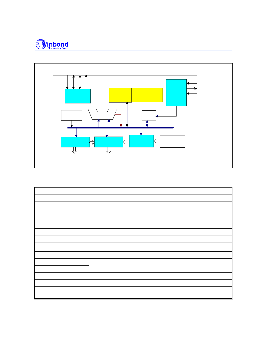
BLOCK DIAGRAM
I/O
Controller
TrueMelody
Generator
RAM
Special Register
Timing
Generator
OSCI
OSCO
P0 P1 P2 P3
Synthesizer II
Synthesizer I
ALU
Timer
ROM
Timbre
Table
DAC1
DAC2
OSCSEL
PAD DESCRIPTION
PARAMETER
I/O
DESCRIPTION
TEST
I
Test pin, internally pulled low
P0.0
-
P0.3
I
Interruptable input pins, internally pulled high.
P1.0
-
P1.3
I/O
I/O multiplexed port 1. The port 1 is interruptable, if selected as input
pins
P2.0
-
P2.3
I/O
I/O multiplexed port 2.
P3.0
-
P3.3
O
Output port 3.
V
SS
-
Negative power supply.
RESET
I
Reset all, functions as POR (Power On Reset), internally pulled high.
V
DD
-
Positive power supply.
OSCI
I
Connect R
OSC
to V
DD
or Crystal between OSCI & OSCO to generate
OSCO
O
the 3 MHz master frequency.
DAC1
O
Current output of channel 1 for driving an external speaker
DAC2
O
Current output of channel 2 for driving an external speaker
OSCSEL
I
Oscillator type selecting pin, internally kept floating. Connect to V
DD
to
select Crystal type, connect to GND to select ring oscillator type.

W561XXX
Publication Release Date: February 1999
- 5 - Revision A2
ABSOLUTE MAXIMUM RATINGS
PARAMETER
SYMBOL
CONDITIONS
RATED VALUE
UNIT
Power Supply
V
DD
-
V
SS
-
-0.3 to +7.0
V
Input Voltage
V
IN
All Inputs
V
SS
-0.3 to V
DD
+0.3
V
Storage Temp.
T
STG
-
-55 to +150
∞
C
Operating Temp.
T
OPR
-
0 to +70
∞
C
Note: Exposure to conditions beyond those listed under Absolute Maximum Ratings may adversely affect the life and reliability of the
device.
ELECTRICAL CHARACTERISTICS
DC Characteristics
(V
DD
-
V
SS
= 3.0V, F
M
= 3 MHz, T
A
= 25
∞
C; unless otherwise specified)
PARAMETER
SYM.
CONDITIONS
MIN.
TYP.
MAX.
UNIT
Operating Voltage
V
DD
-
2.4
-
5.5
V
Standby Current
I
DD1
No load, No Playing
-
-
2
µ
A
Operating Current
(Crystal Type)
I
OP1
No load
-
-
1
mA
Operating Current
(Ring Type)
I
OP2
No load
-
-
1
mA
Input Low Voltage
V
IL
All Input Pins
V
SS
-
0.3 V
DD
V
Input High Voltage
V
IH
All Input Pins
0.7
V
DD
-
V
DD
V
Input Current for P0, P1, P2
I
IN
V
DD
= 3V, V
IN
= 0V
-
-
-6
µ
A
Input Current for
RESET
I
IN1
V
DD
= 3V, V
IN
= 0V
-
-
-6
µ
A
Output Current of P1,
I
OL
V
DD
= 3V, V
OUT
= 0.4V
5
-
-
mA
P2, P3
I
OH
V
DD
= 3V, V
OUT
= 2.7V
-3
-
-
mA
DAC1/2 (D/A full Scale)
I
DAC
V
DD
= 4.5V, R
L
= 100
-4.0
-5.0
-6.0
mA
Pull-low Resistor
R
PL
TEST, OSCSEL Pins
100
-
-
K