
W562XXX DAta Sheet
DUAL-TONE MELODY WITH
VOICE SYNTHESIZER (BandDirector
TM
Series)
Publication Release Date: June 3, 2003
- 1 - Revision A5
Table of Contents-
1.
GENERAL DESCRIPTION ......................................................................................................... 2
2.
FEATURES ................................................................................................................................. 2
3.
BLOCK DIAGRAM ...................................................................................................................... 5
4.
PAD DESCRIPTION ................................................................................................................... 5
5.
ELECTRICAL CHARACTERISTICS........................................................................................... 6
5.1
Absolute Maximum Ratings............................................................................................... 6
5.2
DC Characteristics............................................................................................................. 6
5.3
AC Characteristics............................................................................................................. 6
6.
APPLICATION CIRCUIT............................................................................................................. 7
7.
REVISION HISTORY .................................................................................................................. 8

W562XXX
- 2 -
1. GENERAL DESCRIPTION
The W562xxx is one of the derivatives of the BandDirector
TM
family. It consists of a 4-bit
�C, two voice
synthesizers, one Dual-Tone Melody generator, 38 KHz carrier output for IR transmission and one
ROM shared ROM.
The muti-tasking operation for voice synthesis and Dual-Tone Melody generation is implemented by
dedicated H/W that can output the speech voice in parallel with the background music. The 4 bit
kernel, which executes instructions of up to 12 KIPS (Kilo-Instructions Per Second) can offer
customers a great deal of flexibility to achieve various kind of program controls for different
applications.
In addition, the W562xxx's user-friendly development environment can effectively reduce your design
period and help you easily tool your project by yourself with the W56xxx ICE and emulation kit.
There are 9 kinds of W562xxx IC bodies. (See table below).
PART NO.
W562S08
W562S10
W562S12
W562S15
W562S20
W562S25
W562S30
Duration
8 sec
10 sec
12 sec
15 sec
20 sec
25 sec
30 sec
ROM Size
256 Kbit
288 Kbit
320 Kbit
480 Kbit
576 Kbit
672 Kbit
768 Kbit
PART NO.
W562S40
W562S50
W562S60
W562S80
W562S99
W562M02
Duration
40 sec
50 sec
60 sec
80 sec
100 sec
120 sec
ROM Size
1216 Kbit
1376 Kbit
1536 Kbit
2304 Kbit
2688 Kbit
3072 Kbit
Note: The voice durations are estimated by 6.4 KHz sampling rate
Possible applications are:
� Programmed voice synthesis with background music or speech.
� I/O interactive voice synthesis to accompany background music or speech.
� Q&A games.
� Edutainment toys.
� Remote toys.
2. FEATURES
� Multi-engine processor parallel management with �C, speech and Dual-Tone Melody.
- �C // (Synthesizer1 or Dual-Tone Melody) // Synthesizer2 (//: in parallel )
- �C, with basic ALU, 64-nibble RAM (including 8 working registers) and an 8-bit timer.
The W561 & W562 user RAM initialization value is not constant. It is random. So, user must
initial constant value.
- Synthesizer1 capable of voice syntheses with Sample rate @ 4.8/6/8/12 KHz
- Synthesizer2, same as synthesizer1.
- Dual-tone Melody D/A output with 3 level volume control

W562XXX
Publication Release Date: June 3, 2003
- 3 -
Revision A5
- ICE & ROM chips use different Rosc. Rosc for mass production should check "W562 Freq vs
R.pdf" file for more details.
� Wide operating voltage range: 2.4 to 5.5 volts
� Low power consumption (V
DD
= 5 Volt)
- Standby current < 1 �A
- Operating current < 1 mA
� Main oscillator: 3 MHz, Ring oscillation
� Input/ Output port
- Port for input only: 1 port/ 4 pins
- Input/ Output ports: 2 ports/ 8 pins
- Port for output only: 1 port/ 4 pins
- Can offer a direct row and column matrix of up to 72 (8 � 9) keys
� Interrupts
- Internal interrupts: Timer
- External interrupts: TG (port 0, port1), POI (Power On Initialization)
- Priority: POI > TG > Timer
� Melody + Voice outputs for DAC
� TG interrupt provided
- Share TG interrupt for Port0/Port1 input
- Global TG interrupt enable controlled (bit3 of the IER register)
- Individual interrupt enable controlled (PER0 and PER1 registers)
� Built-in 8 bit programmable down count timer
- One of two internal clock frequencies can be selected
- Desired Timer interval = (preset value+1) * 1/F
T
(F
T
:
32 Hz or 32 KHz dependent on the bit0 of the MODE register, at Fosc = 3 MHz)
� A total of around 64,000 instructions can be used in the program
� Powerful instruction set:
- Arithmetic: ADD, ADDC, SUB, SUBC, INC, DEC, SETB, CLRB
- Logic Operation: AND, OR, XOR, NOT
- Shift & Rotate: RORC, ROLC, SHRC, SHLC
- Date move: LD, LDR, MV
- Branch: JP, JB0, JB1, JB2, JB3, JZ, JNZ, JC, JNC, JBZ1, JBZ2, CJNE, CJE, DJNZ, DJZ
- Subroutine: CALL, RTN, RTI
- Others: NOP, END, EN INT, DIS INT, PLAY CH1, PLAY CH2, STOP CH1, STOP CH2

W562XXX
- 4 -
� 8-level STACK shared by CALL, Timer, Synthesizer and TG
� Multi-tasking operation via interrupt for automatic voice segment concatenation
- Melody or Speech voice can be easily concatenated with symbol "+"
- Example: PLAY CH1, H4 + Melody1 + Speech1 + Speech2 + Melody2 + T4
The DAC of the W562xxx will play Melody1, Speech1, Speech2 and Melody2 sequentially
� The length of the voice segment is unlimited
� Speech section control
- Sample rate control (4.8K/6K/8K/12K)
- Example: PLAY CH2, H4 + speech1_S + T4; S: define the sample rate
� Melody section control
- Background music D/A output bits selectable for volume control (6/7/8)
- Example: PLAY CH1, H4 + Melody_xxB + T4; B: define the melody output bits
� Dual-Tone melody with
- XM3: Triple harmonic effect
- 3 kinds of percussion effects
- 6 beats
- 41 pitches from G3# to C7
- 16 kinds of tempo
- The number of the score and note are unlimited
� Provide IR 38 KHz carrier
- TXF.0 = 0/1 disable/enable IR carrier
- TXF.1 = 0/1 output carrier with P2.3 low/high active
� Provides ICE (In Circuit Emulation) system for easy debugging
- Free Run
- Stop Run
- Program Reset
- Step Into
- Step Over
- Go To Cursor
- Break point
- Register read/ modify
W562XXX
Publication Release Date: June 3, 2003
- 5 -
Revision A5
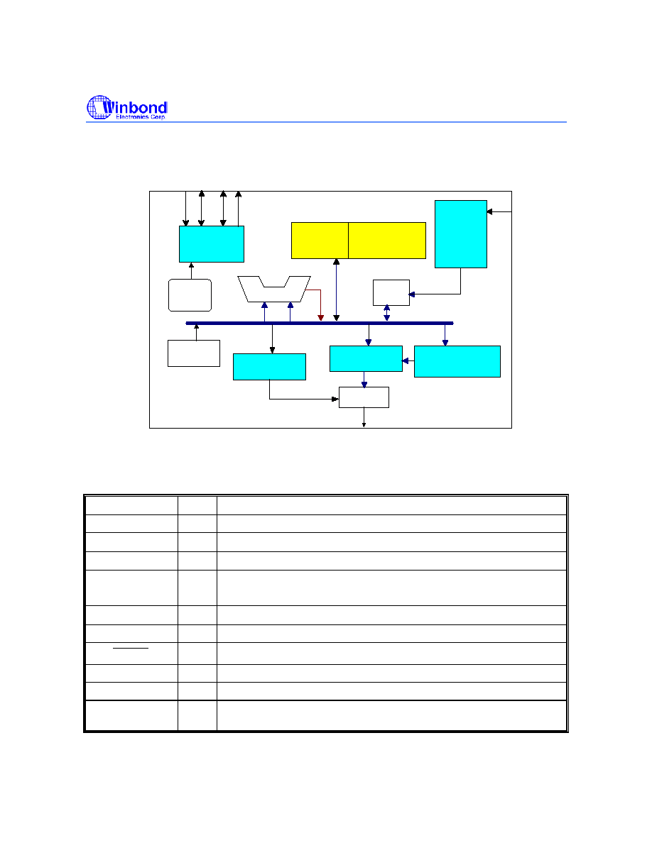
3. BLOCK DIAGRAM
I/O
Controller
Dual Tone
Melody Generator
RAM
Special Register
Timing
Generator
OSC
P0 P1 P2 P3
Synthesizer I
ALU
Timer
ROM
DAC
Mixer
38KHz
carrier
Synthesizer II
*
4. PAD DESCRIPTION
NAME I/O
DESCRIPTION
TEST
I
Test pin, internally pulled low
P0.0
-P0.3
I
Interruptable input pins, internally pulled high
P1.0
-P1.3
I/O
I/O multiplexed port1. Interruptable port if selected as input
P2.0
-P2.3
I/O
I/O multiplexed port 2
P2.3 can be programmed as 38 KHz carrier output pin
P3.0
-P3.3
O
Output port 3
V
SS
-
Negative power supply
RESET
I
Reset all, functions as POR (Power On Reset), internally pulled high
V
DD
-
Positive power supply
OSC I
Connect
R
OSC
to V
DD
to generate 3 MHz oscillator
DAC O
Current output of mixing of the channel 1 and channel 2 for driving an
external speaker