
XECOM
(1)
XE2420
XE2420
March 2002
2400 BPS Surface-Mountable Integrated Sealed-Hybrid Modem
Description
Xecom's XE2420 provides a complete 2400 BPS
modem into an inexpensive miniature, surface-mount
package. Xecom's new HyPLCCTM package (Hybrid
PLCC) makes it possible to meet the conflicting goals
of small size, low cost and surface-mountability. The
XE2420 targets remote monitoring applications in
industrial, commercial and residential locations
As a complete modem, the XE2420 includes not only
all modem circuitry but also user transferrable FCC
Part 68 Registration and UL60950 recognition. This
allows the XE2420 to be safely integrated into your
embedded application.
Xecom's new HyPLCCTM package infuses the XE2420
with both its small size and surface mountability. The
HyPLCC package allows complex hybrid circuits to fit
the 68-Pin PLCC footprint. The HyPLCCTM package
provides a completely sealed enviroment protecting
the XE2420 during assembly and board cleaning
operations.
Features
* Small Size: The HyPLCCTM measures less than 1
inch by 1inch square and 0.290 inches thick
* Surface-mountabile: The HyPLCCTM package is
equivalent to a 68-Pin PLCC device.
* Data transfer at 2400, 1200 and 300 BPS using
V.22bis, V.22, V.23, V.21, Bell 202, Bell 212A, and
Bell 103 Protocols
* Modem Control and Configuration via industry
standard AT Commands.
* Supports external shared line features permitting
unobtrusive sharing of a local telephone line.
* Complete integrated DAA includes, Ring Detect,
Loop Current Holding Circuit, Hook Switch. Metalic
Surge Protection, and Telephone Line Transformer
* User Transferrable FCC Part 68 Registration
* UL60950 Recognition
* Low Power operation, 330 milliWatt; Power down
operation less than 1 microWatt
XE2420 BLOCK DIAGRAM
XECOM
(2)
XE2420
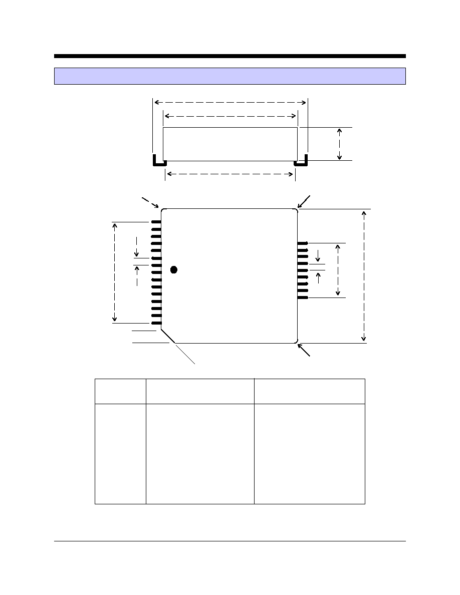
XE2420 Mechanical Specifications
a
b
c
d
c
f
g
e
e
45
O
i
(TOP)
Inches
Millimeters
Dimension
Min
Typ
Max
Min
Typ
Max
a
0.280
0.285
0.290
7.11
7.24
7.37
b
0.985
0.990
0.995
25.02
25.15
25.27
c
0.950
0.955
0.960
24.13
24.26
24.38
d
0.910
0.920
0.930
23.11
23.37
23.62
e
0.045
0.050
0.055
1.15
1.27
1.40
f
0.695
0.700
0.705
17.65
17.78
17.91
g
0.395
0.400
0.405
10.03
10.16
10.29
i(radius)
0.015
0.020
0.025
0.13
0.25
0.38
i
i
.050"

XECOM
(3)
XE2420
XE2420 Pin Configuration
Pin Descriptions
PIN
NAME
DESCRIPTION
1
/DCD
/DCD is an active low output from the modem. The AT&C command controls when the
XE2420 asserts /DCD.
2
/CTS
/CTS is an active low output from the modem. The modem asserts /CTS to indicate that it can
accept data from the terminal equipment on /TXD.
3
RESET
RESET is an active high input which intiates a modem hardware reset. RESET must be active
for a minimum of 100 milliseconds for a proper modem reset sequence. No external reset is
required; if none is used the RESET signal should be left open.
4
/DSR
/DSR is an active low output from the modem. The AT&S command controls when the XE2420
asserts /DSR.
5
/RTS
/RTS is an active low input to the modem. /RTS indicates to the modem that the host has data
to send.
6
/DTR
/DTR is an active low input to the modem. The AT&D command determines how the modem
will interpret activity on /DTR.
7
/RXD
/RXD provides the path for received data and modem responses to be sent from the modem to
the host terminal equipment.
/DCD
1
/CTS
2
RESET
3
/DSR
4
24
RING
/RTS
5
23
N/C
/DTR
6
22
TIP
/RXD
7
21
N/C
/TXD
8
20
N/C
/RI
9
19
HI3
GND
10
18
HI1
N/C
11
17
CD
EECL
12
16
HI2
EEDT
13
Vcc
14
Vui
15
TOP

XECOM
(4)
XE2420
8
/TXD
/TXD provides the path for transmitted data and modem commands to be passed from the host
terminal equipment to the modem.
9
/RI
The /RI signal reports on the presence of an incoming ring signal. When a ring occurs across
Tip and Ring, the /RI output toggles at the ring frequency. The /RI output is powered by Vui
and therefore operates even when VCC is removed from the modem.
10
Ground
Ground provides the reference voltage for all host interface signals.
11
N/C
No internal connection
12
EECL
EECL provides the clock to the optional external non-volatile memory. The XE2420 requires
a serial 8 by 256 Byte EEPROM for telephone number storage. If the non-volatile memory is
not used, EECL should remain unconnected.
13
EEDT
EEDT provides the serial data connection for the optional, external non-volatile memory. The
XE2420 requires a serial 8 by 256 Byte EEPROM for telephone number storage. If the non-
volatile memory is not used, EEDT should remain unconnected.
14
VCC
VCC provides 5 volt power to the modem. The RI output is not powered by VCC but by Vui.
15
Vui
Vui provides uninterrupted power to the XE2420 ring detect circuit. Placing 5 volt power on
Vui insures that the /RI ouput will operate when VCC is removed from the modem.
16
HI2
HI2 is one of the four hardware hooks for connecting shared line features to the XE2420.
HI2 interfaces to the 911 Interrupt circuit. This circuit detects changes in the loop current
when an extension handset is lifted as when making an emergency call. The system host
should immediately abort the modem connection to permit the user to complete their call.
See the Application Note on Page 10 of this data sheet to see how these line monitoring
circuits interface with the XE2420.
17
CD
CD provides another of the four hardware hooks for connecting shared line features to the
XE2420. CD interfaces to the Connect Dectect circuit. Connect Detect allows the system
host to check the status of the telephone line before going off-hook to initiate a call. If the
phone line is in use,the host can delay its call until the telephone line is free. See the
Application Note on Page 10 of this data sheet to see how these line monitoring circuits
interface with the XE2420.
18
HI1
HI1 is one of the four hardware hooks for connecting shared line features to the XE2420.
HI1 interfaces to the 911 Interrupt circuit. This circuit detects changes in the loop current
when an extension handset is lifted as when making an emergency call. The system host
should immediately abort the modem connection to permit the user to complete their call.
See the Application Note on Page 9 of this data sheet to see how these line monitoring
circuits interface with the XE2420.
XE2420 Pin Descriptions (continued)
PIN
NAME
DESCRIPTION

XECOM
(5)
XE2420
XE2420 Pin Descriptions (continued)
PIN
NAME
DESCRIPTION
19
HI3
HI3 is one of the four hardware hooks for connecting shared line features to the XE2420.
HI3 interfaces to the 911 Interrupt circuit. This circuit detects changes in the loop current
when an extension handset is lifted as when making an emergency call. The system host
should immediately abort the modem connection to permit the user to complete their call.
See the Application Note on Page 10 of this data sheet to see how these line monitoring
circuits interface with the XE2420.
20
N/C
No internal connection, To prevent damage in case of voltage surges on the telephone line, we
recommend that nothing be connected to this pin.
21
N/C
No internal connection, To prevent damage in case of voltage surges on the telephone line, we
recommend that nothing be connected to this pin.
22
Tip
The Ring and Tip signals provide modem the connection to the telephone line. FCC Part 68
Rules require a 1500 volt isolation barrier between the telephone line and all other circuits.
This isolation must be preserved throughout the system.
The telephone company places a DC "Battery" voltage across Tip and Ring on all public switched
telephone lines. The XE2420 will operate regardless of the polarity of this "Battery" voltage.
The "Battery" voltage drives up to 100 milliamps of DC loop current.
UL60950 requires minimum creepage and clearances distances be maintained between the
Tip and Ring traces and all other circuits. Clearance is the shortest distance between conductive
circuits; creepage is the distance between conductive surfaces along the surface
23
N/C
No internal connection, To prevent damage in case of voltage surges on the telephone line, we
recommend that nothing be connected to this pin.
24
Ring
The Ring and Tip signals provide modem the connection to the telephone line. FCC Part 68
Rules require a 1500 volt isolation barrier between the telephone line and all other circuits.
This isolation must be preserved throughout the system.
The telephone company places a DC "Battery" voltage across Tip and Ring on all public switched
telephone lines. The XE2420 will operate regardless of the polarity of this "Battery" voltage.
The "Battery" voltage drives up to 100 milliamps of DC loop current.
UL60950 requires minimum creepage and clearances distances be maintained between the
Tip and Ring traces and all other circuits. Clearance is the shortest distance between conductive
circuits; creepage is the distance between conductive surfaces along the surface.