
XECOM
(1)
XE900SL10
XE900SL10
November 2003
XE900S World's Smallest Spread Spectrum Smart Transceiver
Description
The XE900SL10 breaks new ground in Smart Transceiver
Technology. Never before has a 900 MHz, Spread
Spectrum Transceiver with integral micro-controller been
this small, just 1 inch square. This miniature size
combined with extremely low power consumption make
the XE900SL10 perfect for portable and battery powered
applications.
Xecom did not compromise of features to reduce the
size. The XE900SL10 still supports Xecom's Count-Off
feature enabling a scan of all 253 remote nodes in under
10 seconds. SensorOnAir is included so that sensors
and control lines can utilize the transceivers
communications controller in place of a second micro-
controller .
The XE900SL10 transmits at up to 10 milliwatts and has
a maximum receive sensitivity of -100 dBm. This insures
that the XE900SL10 can support an indoor
communications range of 200 feet through walls and
ceilings. All of this while operating from a 3.3 volt power
source. By virtue of its miniature package and low
power consumption Xecom's XE900SL10 can be used
when no other transceiver can be.
XE900SL10 Block Diagram
Features
* Small Size: 1.0" by 1.0" by 0.26"
* Serial Control and Configuration of the Wireless Link.
* Supports a 254 node point-to-multipoint network
* Output Power Programmable from 0 to 10 mW;
* Maximum Receiver Sensitivity -100 dBm
* Obstructed signal range to 200 feet;
* Wireless Data Rate 76.8K bps, half-duplex;
* Power Consumption:
50 mA @ 3.3 Volts when transmitting at 1 mW
15 mA at idle
<10 uA in Power Down Mode
* SensorOnAir
TM
allows direct connection of sensors to
the Smart Transceiver
* Count Off
TM
allows the master node to download the
status of all nodes in under 10 seconds.
* Operating Temperature Range of -40 to +85 C
* FCC Part 15 Registered
Analog
Inputs
Antenna
Serial
I/F
Digital
I/O
UHF
TRANSCEIVER
SAW
FILTER
CO
M
M
U
N
I
CA
T
I
O
N
S
CO
N
T
R
O
L
L
E
R
ROM
MUX
Preliminary

XECOM
(2)
XE900SL10
XE900S MECHANICAL SPECIFICATIONS
Dimension Description
Inches
M M
A
Module Width
1.00
25.40
B
Max.Module Thickness
0.30
7.62
C
Row to Row
0.90
22.86
D
Minimum Lead Length
0.10
2.54
E
Module Length
1.00
25.40
F
Pin 10 to Pin15
0.50
12.70
G
Pin 10 to Edge
0.40
10.16
H
Pin 1 to Pin 9
0.80
20.32
J
Pin to Pin Spacing
0.10
2.54
K
Pin 1, 9, or 15 to Edge
0.10
2.54
A
B
Top View
C
D
E
H
F
G
K
J

XECOM
(3)
XE900SL10
XE900S PIN CONFIGURATION
SIGNAL
PINS
DESCRIPTION
/RXD
1
Received Data is the data output from the XE900SL10.
/TXD
2
Transmit Data is the data input to the XE900SL10.
/CTS
3
Clear to Send provides hardware flow control from the XE900SL10. The XE900SL10
drives /CTS high to signal the host to temporarily stop the flow of data into /TXD.
/RTS
4
Request to Send provides hardware flow control from the host system. The host system
drives /RTS high to signal the XE900SL10 to temporarily stop the data flow onto /RXD.
DIO3
5
DIO0 may be programmed as either a digital input or digital output. It connects directly to
the communications controller in the XE900SL10.
DIO2
6
DIO2 may be programmed as either a digital input or digital output. It connects directly to
the communications controller in the XE900SL10.
DIO1
7
DIO1 may be programmed as either a digital input or digital output. It connects directly to
the communications controller in the XE900SL10.
DIO0
8
DIO0 may be programmed as either a digital input or digital output. It connects directly to
the communications controller in the XE900SL10.
N/C
9
No Connection
N/C
10
No Connection
Reset
11
Provides an active high hardware reset to the XE900SL10.
ADC0
12
Analog Input 0 to the XE900SL10's communications controller. ADC0 connects to an
internal 10-bit Analog to Digital Convertor. ADC0 may also be configured as a digital
input if no analog inputs are required.
ADC1
13
Analog Input 1 to the XE900SL10's communications controller. ADC1 connects to an
internal 10-bit Analog to Digital Convertor. ADC0 may also be configured as a digital
input if no analog inputs are required.
Ground
14
Common voltage reference for the XE900SL10.
VCC
15
3.3 Volt power for the XE900SL10.
XE900SL10
Top View
/RXD
1
15
VCC
/TXD
2
14
Gnd
/CTS
3
13
ADC1
/RTS
4
12
ADC0
DIO3
5
11
Reset
DIO2
6
10
N/C
DIO1
7
DIO0
8
Antenna
N/C
9

XECOM
(4)
XE900SL10
ABSOLUTE MAXIMUM RATINGS
VCC
3.9 Volts
Storage Temperature
-55
O
C to +125
O
C
Operating Temperature Range
-40
O
C to +85
O
C
WARNING: Exceeding any of these ratings will void the warranty and may damage the device
XE900SL10 ELECTRICAL SPECIFICATIONS
VCC
2.7
3.3
3.6
Volts
Transceiver power
ICC
50
mA
Transmit Mode (1 mW output)
30
mA
Receive Mode
15
mA
Idle Mode
10
uA
Sleep Mode
Output Power: XE900S-10
0
10
mW
50 Ohm Load
Wireless Receive Sensitivity
-100
dBm
Frequency Hopping Channels
63
Frequency Range
902
928
MHz
Communications Range
200
ft.
Antenna Output Impedance
50
Ohms
Latency
TBD
ms
Voh
.2.25
Volts
VCC =3.3 Volts
Vol
0.75
Volts
VCC =3.3 Volts
Vih
2.25
Volts
VCC =3.3 Volts
Vil
0.75
Volts
VCC =3.3 Volts
Parameter
Min
Typ
Max
Units
Comments
XECOM
(5)
XE900SL10
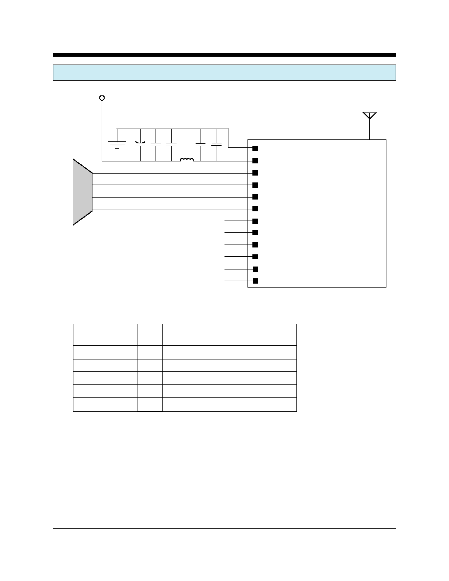
XE900SL10 TYPICAL CONNECTION DIAGRAM
GND
VCC
/RXD
/TXD
/CTS
/RTS
DIO3
DIO2
DIO1
DIO0
ADC1
ADC0
Antenna
Host
Serial
I/F
3.3V
C1 C2 C3 C4 C5
L1
Parts List for XE900SL10 Typical Connection Diagram
Reference
Designation
Qty
Description
C1
1
Capacitor, Electrolytic, 100 ufd, 10 Volts
C2, C4
2
Capacitor 0.1 ufd, 10 Volts
C3, C5
2
Capacitor 47 pfd, 10 Volts
L1
1
Coilcraft 0603HC-7N5XJB
Antenna *
1
50 Ohm, 1/4 Wave
* The Antenna connector on the XE900SSL10 is a Male MMCX
connector. An femle MMCZ to Female SMA adapter will be need for
the antenna connection