 | –≠–ª–µ–∫—Ç—Ä–æ–Ω–Ω—ã–π –∫–æ–º–ø–æ–Ω–µ–Ω—Ç: XC4013 | –°–∫–∞—á–∞—Ç—å:  PDF PDF  ZIP ZIP |

2-47
XC4000
Logic Cell Array Family
Æ
Product Specifications
Description
The XC4000 family of Field-Programmable Gate Arrays
(FPGAs) provides the benefits of custom CMOS VLSI,
while avoiding the initial cost, time delay, and inherent risk
of a conventional masked gate array.
The XC4000 family provides a regular, flexible, program-
mable architecture of Configurable Logic Blocks (CLBs),
interconnected by a powerful hierarchy of versatile routing
resources, and surrounded by a perimeter of program-
mable Input/Output Blocks (IOBs).
XC4000 devices have generous routing resources to ac-
commodate the most complex interconnect patterns. They
are customized by loading configuration data into the inter-
nal memory cells. The FPGA can either actively read its
configuration data out of external serial or byte-parallel
PROM (master modes), or the configuration data can be
written into the FPGA (slave and peripheral modes).
The XC4000 family is supported by powerful and sophisti-
cated software, covering every aspect of design: from
schematic entry, to simulation, to automatic block place-
ment and routing of interconnects, and finally the creation
of the configuration bit stream.
Since Xilinx FPGAs can be reprogrammed an unlimited
number of times, they can be used in innovative designs
where hardware is changed dynamically, or where hard-
ware must be adapted to different user applications. FPGAs
are ideal for shortening the design and development cycle,
but they also offer a cost-effective solution for production
rates well beyond 1000 systems per month.
For a detailed description of the device features, architec-
ture, configuration methods and pin descriptions, see
pages 2-9 through 2-45.
Features
∑
Third Generation Field-Programmable Gate Arrays
≠ Abundant flip-flops
≠ Flexible function generators
≠ On-chip ultra-fast RAM
≠ Dedicated high-speed carry-propagation circuit
≠ Wide edge decoders (four per edge)
≠ Hierarchy of interconnect lines
≠ Internal 3-state bus capability
≠ Eight global low-skew clock or signal distribution
network
∑
Flexible Array Architecture
≠ Programmable logic blocks and I/O blocks
≠ Programmable interconnects and wide decoders
∑
Sub-micron CMOS Process
≠ High-speed logic and Interconnect
≠ Low power consumption
∑
Systems-Oriented Features
≠ IEEE 1149.1-compatible boundary-scan logic support
≠ Programmable output slew rate (2 modes)
≠ Programmable input pull-up or pull-down resistors
≠ 12-mA sink current per output
≠ 24-mA sink current per output pair
∑
Configured by Loading Binary File
≠ Unlimited reprogrammability
≠ Six programming modes
∑
XACT Development System runs on '386/'486-type PC,
NEC PC, Apollo, Sun-4, and Hewlett-Packard 700
series
≠ Interfaces to popular design environments like
Viewlogic, Mentor Graphics and OrCAD
≠ Fully automatic partitioning, placement and routing
≠ Interactive design editor for design optimization
≠ 288 macros, 34 hard macros, RAM/ROM compiler
Device
XC4003
XC4005
XC4006
XC4008 XC4010/10D
XC4013
XC4020
XC4025
Appr. Gate Count
3,000
5,000
6,000
8,000
10,000
13,000
20,000
25,000
CLB Matrix
10 x 10
14 x 14
16 x 16
18 x 18
20 x 20
24 x 24
28 x 28
32 x 32
Number of CLBs
100
196
256
324
400
576
784
1,024
Number of Flip-Flops
360
616
768
936
1,120
1,536
2,016
2,560
Max Decode Inputs (per side)
30
42
48
54
60
72
84
96
Max RAM Bits
3,200
6,272
8,192
10,368
12,800*
18,432
25,088
32,768
Number of IOBs
80
112
128
144
160
192
224
256
*XC4010D has no RAM
Table 1. The XC4000 Family of Field-Programmable Gate Arrays
2-48
XC4000 Logic Cell Array Family
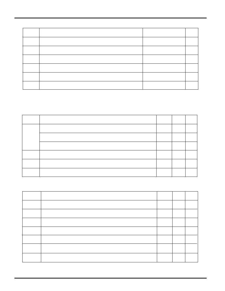
Absolute Maximum Ratings
Symbol
Description
Units
V
CC
Supply voltage relative to GND
≠0.5 to +7.0
V
V
IN
Input voltage with respect to GND
≠0.5 to V
CC
+0.5
V
V
TS
Voltage applied to 3-state output
≠0.5 to V
CC
+0.5
V
T
STG
Storage temperature (ambient)
≠65 to + 150
∞
C
T
SOL
Maximum soldering temperature (10 s @ 1/16 in. = 1.5 mm)
+ 260
∞
C
T
J
Junction temperature
+ 150
∞
C
Note:
Stresses beyond those listed under Absolute Maximum Ratings may cause permanent damage to the device.
These are stress ratings only, and functional operation of the device at these or any other conditions beyond
those listed under Recommended Operating Conditions is not implied. Exposure to Absolute Maximum Ratings
conditions for extended periods of time may affect device reliability.
Operating Conditions
Symbol
Description
Min
Max
Units
V
CC
Supply voltage relative to GND Commercial 0
∞
C to 85
∞
C junction
4.75
5.25
V
Supply voltage relative to GND Industrial -40
∞
C to 100
∞
C junction
4.5
5.5
V
Supply voltage relative to GND
Military ≠55
∞
C to 125
∞
C case
4.5
5.5
V
V
IH
High-level input voltage (XC4000 has TTL-like input thresholds)
2.0
V
CC
V
V
IL
Low-level input voltage (XC4000 has TTL-like input thresholds)
0
0.8 V
T
IN
Input signal transition time
250
ns
DC Characteristics Over Operating Conditions
Symbol
Description
Min
Max
Units
V
OH
High-level output voltage @ I
OH
= ≠4.0 mA, V
CC
min
2.4
V
V
OL
Low-level output voltage @ I
OL
= 12.0 mA, V
CC
min (Note 1)
0.4
V
I
CCO
Quiescent LCA supply current (Note 2)
10
mA
I
IL
Leakage current
≠10
+10
µ
A
C
IN
Input capacitance (sample tested)
15
pF
I
RIN
Pad pull-up (when selected) @ V
IN
= 0V (sample tested)
0.02
0.25
mA
I
RLL
Horizontal Long Line pull-up (when selected) @ logic Low
0.2
2.5
mA
Note: 1. With 50% of the outputs simultaneously sinking 12 mA.
2. With no output current loads, no active input or longline pull-up resistors, all package pins at V
CC
or GND, and
the LCA configured with a MakeBits tie option.
At junction temperatures above those listed as Operating Conditions, all delay parameters increase by 0.35% per
∞
C.
2-49
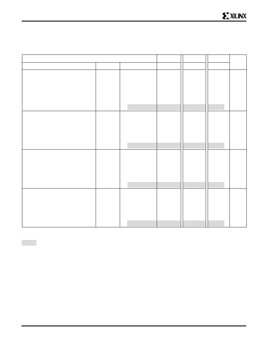
Wide Decoder Switching Characteristic Guidelines
Testing of the switching parameters is modeled after testing methods specified by MIL-M-38510/605. All devices are 100%
functionally tested. Since many internal timing parameters cannot be measured directly, they are derived from benchmark timing
patterns. The following guidelines reflect worst-case values over the recommended operating conditions. For more detailed, more
precise, and more up-to-date timing information, use the values provided by the XACT timing calculator and used in the simulator.
Speed Grade
-6
-5
-4
Description
Symbol
Device
Max
Max
Max
Units
Full length, both pull-ups,
T
WAF
XC4003
9.0
8.0
5.0
ns
inputs from IOB I-pins
XC4005
10.0
9.0
6.0
ns
XC4006
11.0
10.0
7.0
ns
XC4008
12.0
11.0
8.0
ns
XC4010
13.0
12.0
9.0
ns
XC4013
15.0
14.0
11.0
ns
XC4025
21.0
19.0
17.0
ns
Full length, both pull-ups
T
WAFL
XC4003
12.0
11.0
7.0
ns
inputs from internal logic
XC4005
13.0
12.0
8.0
ns
XC4006
14.0
13.0
9.0
ns
XC4008
15.0
14.0
10.0
ns
XC4010
16.0
15.0
11.0
ns
XC4013
18.0
17.0
13.0
ns
XC4025
24.0
23.0
20.0
ns
Half length, one pull-up
T
WAO
XC4003
9.0
8.0
6.0
ns
inputs from IOB I-pins
XC4005
10.0
9.0
7.0
ns
XC4006
11.0
10.0
8.0
ns
XC4008
12.0
11.0
9.0
ns
XC4010
13.0
12.0
10.0
ns
XC4013
15.0
14.0
12.0
ns
XC4025
21.0
19.0
18.0
ns
Half length, one pull-up
T
WAOL
XC4003
12.0
11.0
8.0
ns
inputs from internal logic
XC4005
13.0
12.0
9.0
ns
XC4006
14.0
13.0
10.0
ns
XC4008
15.0
14.0
11.0
ns
XC4010
16.0
15.0
12.0
ns
XC4013
18.0
17.0
14.0
ns
XC4025
24.0
23.0
21.0
ns
Note: These delays are specified from the decoder input to the decoder output. For pin-to-pin delays, add the input delay (T
PID
)
and output delay (T
OPF
or T
OPS
), as listed on page 2-52.
PRELIMINARY

2-50
XC4000 Logic Cell Array Family
Speed Grade
-6
-5
-4
Description
Symbol
Device
Max
Max
Max
Units
Global Signal Distribution
From pad through primary buffer, to any clock K
T
PG
XC4003
7.8
5.8
5.1
ns
XC4005
8.0
6.0
5.5
ns
XC4006
8.2
6.2
5.7
ns
XC4008
8.6
6.6
6.1
ns
XC4010
9.0
7.0
6.5
ns
XC4013
10.0
8.0
7.5
ns
XC4025
17.0
15.0
14.5
ns
From pad through secondary buffer, to any clock K
T
SG
XC4003
8.8
6.8
6.3
ns
XC4005
9.0
7.0
6.7
ns
XC4006
9.2
7.2
6.9
ns
XC4008
9.6
7.6
7.3
ns
XC4010
10.0
8.0
7.7
ns
XC4013
11.0
9.0
8.7
ns
XC4025
18.0
16.0
15.7
ns
Speed Grade
-6
-5
-4
Description
Symbol
Device
Max
Max
Max
Units
TBUF driving a Horizontal Longline (L.L.)
T
IO1
XC4003
8.8
6.2
4.4
ns
I going High or Low to L.L. going High or Low,
XC4005
10.0
7.0
5.5
ns
while T is Low, i.e. buffer is constantly active
XC4006
10.6
7.5
6.0
ns
XC4008
11.1
8.0
6.5
ns
XC4010
11.7
8.5
7.0
ns
XC4013
13.0
9.5
7.5
ns
XC4025
20.0
16.5
14.5
ns
I going
Low to L.L. going from resistive pull-up
T
IO2
XC4003
9.3
6.7
5.0
ns
High to active Low, (TBUF configured as open drain)
XC4005
10.5
7.5
6.0
ns
XC4006
11.1
8.0
6.5
ns
XC4008
11.6
8.5
7.0
ns
XC4010
12.2
9.0
7.5
ns
XC4013
13.5
10.0
8.0
ns
XC4025
23.5
20.0
18.0
ns
T going Low to L.L. going from resistive pull-up or
T
ON
XC4003
10.7
9.0
7.2
ns
floating High to active Low, (TBUF configured as
XC4005
12.0
10.0
8.0
ns
open drain or active buffer with I = Low)
XC4006
12.6
10.5
8.5
ns
XC4008
13.2
11.0
9.0
ns
XC4010
13.8
11.5
9.5
ns
XC4013
15.1
12.6
11.1
ns
XC4025
23.0
20.5
19.0
ns
T going High to TBUF going inactive, not driving L.L.
T
OFF
All devices
3.0
2.0
1.8
ns
T going High to L.L. going from Low to High,
T
PUS
XC4003
24.0
20.0
14.0
ns
pulled up by a single resistor
XC4005
26.0
22.0
16.0
ns
XC4006
28.0
24.0
18.0
ns
XC4008
30.0
26.0
20.0
ns
XC4010
32.0
28.0
22.0
ns
XC4013
36.0
32.0
26.0
ns
XC4025
52.0
48.0
42.0
ns
T going High to L.L. going from Low to High,
T
PUF
XC4003
11.6
9.0
7.0
ns
pulled up by two resistors
XC4005
12.0
10.0
8.0
ns
XC4006
13.0
11.0
9.0
ns
XC4008
14.0
12.0
10.0
ns
XC4010
15.0
13.0
11.0
ns
XC4013
17.0
15.0
13.0
ns
XC4025
24.0
22.0
20.0
ns
Global Buffer Switching Characteristic Guidelines
Testing of the switching parameters is modeled after testing methods specified by MIL-M-38510/605. All devices are 100%
functionally tested. Since many internal timing parameters cannot be measured directly, they are derived from benchmark timing
patterns. The following guidelines reflect worst-case values over the recommended operating conditions. For more detailed, more
precise, and more up-to-date timing information, use the values provided by the XACT timing calculator and used in the simulator.
Horizontal Longline Switching Characteristic Guidelines
Testing of the switching parameters is modeled after testing methods specified by MIL-M-38510/605. All devices are 100%
functionally tested. Since many internal timing parameters cannot be measured directly, they are derived from benchmark timing
patterns. The following guidelines reflect worst-case values over the recommended operating conditions. For more detailed, more
precise, and more up-to-date timing information, use the values provided by the XACT timing calculator and used in the simulator.
PRELIMINARY
2-51
Pad to I1, I2
via transparent
latch, with delay
XC4003 17.6 ns
XC4005 17.9 ns
XC4006 18.0 ns
XC4008 18.3 ns
XC4010 18.6 ns
XC4013 19.3 ns
XC4025 23.5 ns
T
PDLI
for -4 Speed Grade
Input set-up time
pad to clock (IK)
with delay
XC4003 15.6 ns
XC4005 15.9 ns
XC4006 16.0 ns
XC4008 16.3 ns
XC4010 16.6 ns
XC4013 17.3 ns
XC4025 22.5 ns
T
PICKD
for -4 Speed Grade
X6082
Speed Grade
-6
-5
-4
Description
Symbol
Device
Units
Global Clock to Output (fast) using OFF
T
ICKOF
XC4003
15.1
12.5
11.6
ns
XC4005
15.5
13.0
12.0
ns
XC4006
15.7
13.2
12.2
ns
(Max)
XC4008
16.1
13.6
12.6
ns
XC4010
16.5
14.0
13.0
ns
XC4013
17.5
15.0
14.0
ns
XC4025
25.5
22.0
21.0
ns
Global Clock to Output (slew limited) using OFF
T
ICKO
XC4003
19.9
15.2
14.4
ns
XC4005
20.5
16.0
15.0
ns
XC4006
20.7
16.2
15.2
ns
(Max)
XC4008
21.1
16.6
15.6
ns
XC4010
21.5
17.0
16.0
ns
XC4013
22.5
18.0
17.0
ns
XC4025
29.5
25.0
24.0
ns
Input Set-up Time, using IFF (no delay)
T
PSUF
XC4003
2.4
2.0
1.6
ns
XC4005
2.0
1.5
1.2
ns
XC4006
1.8
1.3
1.0
ns
(Min)
XC4008
1.4
0.9
0.6
ns
XC4010
1.0
0.5
0.2
ns
XC4013
0.5
0
0
ns
XC4025
0
0
0
ns
Input Hold time, using IFF (no delay)
T
PHF
XC4003
5.1
4.0
4.0
ns
XC4005
5.5
4.5
4.5
ns
XC4006
5.7
4.7
4.7
ns
(Min)
XC4008
6.1
5.1
5.1
ns
XC4010
6.5
5.5
5.5
ns
XC4013
7.5
6.5
6.5
ns
XC4025
18.0
16.0
15.5
ns
Input Set-up Time, using IFF (with delay)
T
PSU
XC4003
21.5
18.5
12.0
ns
XC4005
21.0
18.0
12.0
ns
XC4006
20.8
17.8
12.0
ns
(Min)
XC4008
20.4
17.4
12.0
ns
XC4010
20.0
17.0
12.0
ns
XC4013
19.0
16.0
12.0
ns
XC4025
18.0
15.0
12.0
ns
Input Hold Time, using IFF (with delay)
T
PH
XC4003
0
0
0
ns
XC4005
0
0
0
ns
XC4006
0
0
0
ns
(Min)
XC4008
0
0
0
ns
XC4010
0
0
0
ns
XC4013
0
0
0
ns
XC4025
0
0
0
ns
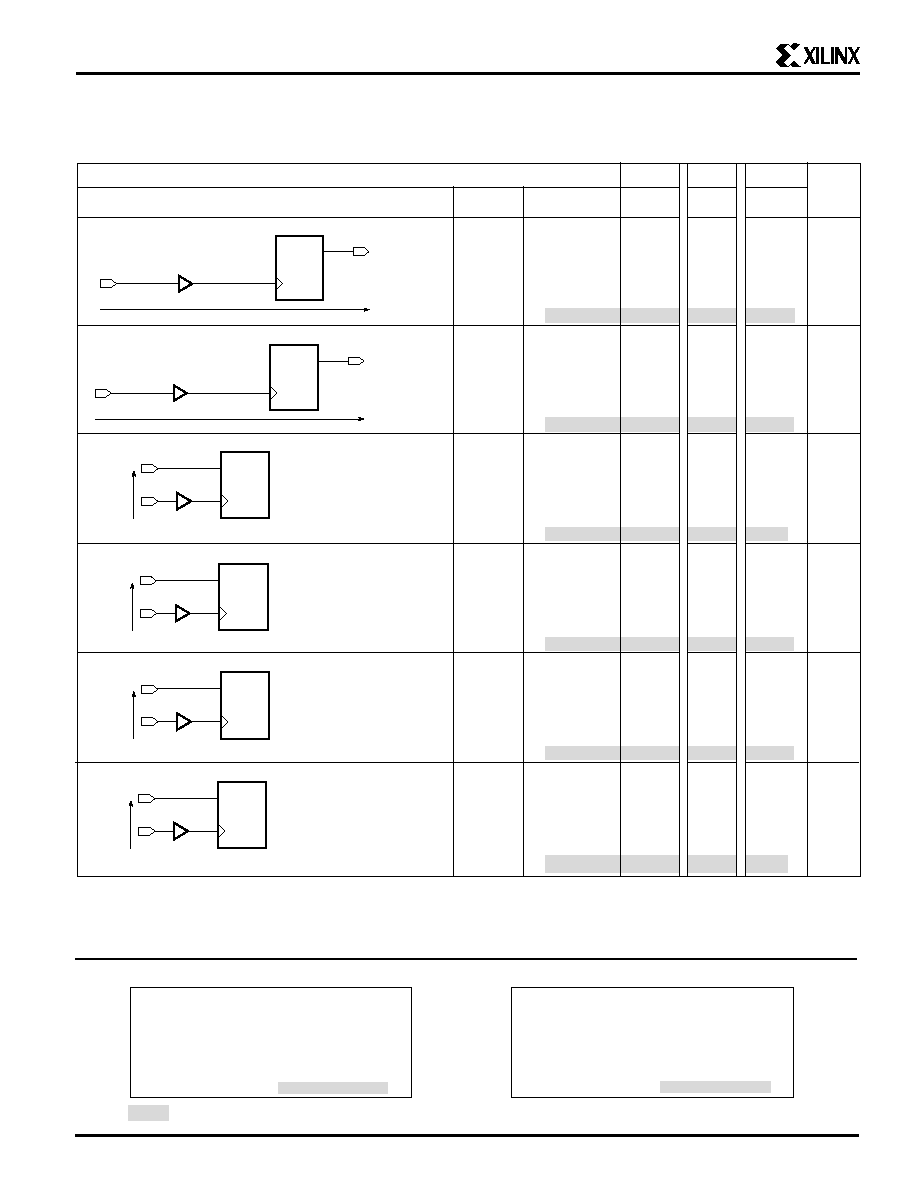
Guaranteed Input and Output Parameters (Pin-to-Pin)
All values listed below are tested directly, and guaranteed over the operating conditions. The same parameters can also be derived
indirectly from the IOB and Global Buffer specifications. The XACT delay calculator uses this indirect method. When there is a
discrepancy between these two methods, the values listed below should be used, and the derived values must be ignored.
OFF
Global Clock-to-Output Delay
.
.
.
.
.
X3202
T
PG
OFF
Global Clock-to-Output Delay
.
.
.
.
.
X3202
T
PG
IFF
Input
Set-Up
&
Hold
Time
X3201
D
T
PG
IFF
Input
Set-Up
&
Hold
Time
X3201
D
T
PG
IFF
Input
Set-Up
&
Hold
Time
X3201
D
T
PG
IFF
Input
Set-Up
&
Hold
Time
X3201
D
T
PG
Timing is measured at pin threshold, with 50 pF external capacitive loads (incl. test fixture). When testing fast outputs, only one
output switches. When testing slew-rate limited outputs, half the number of outputs on one side of the device are switching. These
parameter values are tested and guaranteed for worst-case conditions of supply voltage and temperature, and also with the most
unfavorable clock polarity choice.
PRELIMINARY
See page 2-52