
INTRODUCTION
YTD428 is a LSI which provides the ISDN subscriber interface (two-wire time compression
multiplexing operation) and the NT side of the ISDN Basic Rate user-network interface function
(digital four-wire time-division full-duplex operation). It is capable of providing the electric
characteristics conforming to TTC Standard JT-I430 and JT-G961.
YTD428 incorporates the circuit termination and line termination functions on a single chip
allowing the user to easily configure a DSU (Digital Service Unit) that consumes small amount of
power at a minimal cost.
In addition, a TTL interface is provided at the T reference point (layer 1 level). This feature is
especially effective when combined with YAMAHA's ISDN LSI for S/T reference point interface,
YTD423 or YTD418. It allows considerable cost reduction on parts around the pulse transformer
when constructing a device with a built-in DSU.
The driver/receiver section of the T reference point interface can be separated from the DSU section
and be used independently. The user can enable or disable this feature as necessary.
YTD428 CATALOG
CATALOG No.:4TD428A2
2001.1
YTD428
IDSU
DSU LSI for the ISDN Terminal Equipment

- 2 -
Features
s
Circuit Termination Section
s
Conforms to TTC Standard JT-I430 and JT-G961
q
Digital four-wire time-division full-duplex operation
q
Two-wire time compression multiplexing operation
q
Transmission rate at U reference point: 320 kbit/s, at T reference point: 192 kbit/s
q
Frame assembling and disassembling function
q
State transition control
q
Loopback function
q
T reference point timing control
(switch between short passive bus / extended passive bus, point-to-point)
q
U reference point driver control
s
Line Termination Section
s
Conforms to TTC Standard JT-G961
q
f
equalizer
q
Bridged tap equalizer
s
T Reference Point Interface Section
q
The T reference point driver / receiver section can be separated from DSU section, and use
independently (TE mode). The user can enable or disable this feature as necessary.
s
Others
q
+5 V single power supply
q
100 pin SQFP

- 3 -
BLOCK DIAGRAM
Internal Block Diagram
ADC
CT block
Interface
switch section
TTL I/F
U ref. pt.
driver control
LT block
S/T ref. pt. LSI
YTD418 or
YTD423
T ref. pt. I/F section
U ref. pt. I/F section
YTD428
CT/LT section
T ref. pt.
receiver
T ref. pt.
driver
Peak hold
Variable
Amplifier
T
ref. pt. side
U ref. pt. side
CT : Circuit Termination
LT : Line Termination
- 4 -
DSU Configuration Example
YTD428 incorporates the circuit termination, line termination, T reference point interface and U
reference point interface functions on a single chip allowing the user to easily configure a DSU that
consumes small amount of power at a minimal cost. The user can select from the two types of
configurations. One is the general configuration in which a transformer is used at the T reference
point interface. The other is a configuration in which a TTL interface is used to directly connect to
the T reference point LSI.
s
Configuration example of a general DSU
Various functions are incorporated on a single chip allowing the user to create a low power-consuming
product at a low cost.
YM7405 or
YTD410
for S/T ref. pt.
included driver/receiver
for S/T ref. pt.
YTD428
DSU
L1
TA / TB
RA / RB
L2
Layer 3 info.
Bch data
Call control
circuit
U ref. pt. driver
T ref. pt.
U ref. pt. side

- 5 -
YTD428
DSU section
Call control
circuit
U ref. pt.
driver
Layer 3 information
(Bch data)
TTL I/F
(No transformer is requied)
YTD418 or
YTD423
I/F
switch
CT
and
LT
U ref.
pt. I/F
T ref.
pt. I/F
L1
TA / TB
RA / RB
L2
T
ref. pt. side
(to terminal)
U ref. pt. side
YTD428
DSU section
Call control
circuit
U ref. pt.
driver
YTD418 or
YTD423
I/F
switch
CT
and
LT
U ref.
pt. I/F
T ref.
pt. I/F
TTL I/F
(No transformer is required)
L1
TA / TB
RA / RB
L2
T
ref. pt. side
(DSU)
U ref. pt. side
Layer 3 information
(Bch data)
s
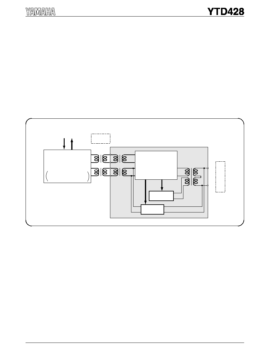
Configuration example of a device with a built-in DSU that uses a TTL interface at
the T ref. pt.
When using YTD428 with YAMAHA'S S/T reference point interface LSI to create a device with a built-in
DSU, they can be connected directly through the TTL interface. This results in a reduction of pulse
transformer parts.
s
Example of using T reference point driver / receiver section independently
By setting the Interface switch, the drive / receiver of the T reference point interface section can be separated
from the circuit termination (CT) and line termination (LT) section and be used independently.
The user can enable or disable this feature as necessary.