1
Features
∑ Data rate up to 622Mbps
∑ 1310, 1550 nm PIN
∑ TIA with AGC
∑ TO-46 Assembly
∑ 3.3V power supply
Applications
∑ Sonet OC-12
∑ SDH STM-4
∑ ATM 622Mbps
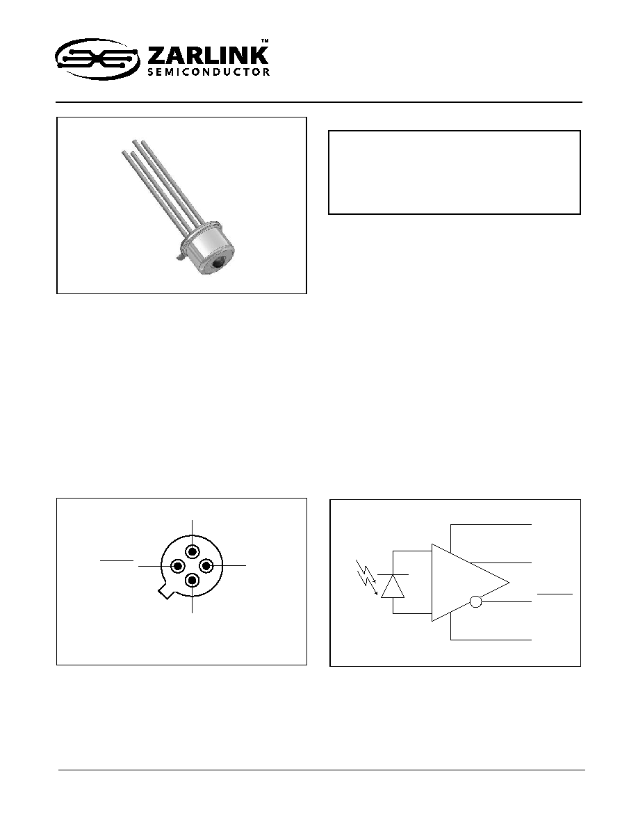
Figure 1 - Pin Diagram
Data Out
V
CC
Data Out
Case
GND
Bottom View
Description
This optical receiver is a 3.3V device which contains
an InGaAs PIN photodiode and a transimpedance
amplifier with Automatic Gain Control and DC restore
circuit assembled in a TO-46 package. It is designed
for ATM and SDH/Sonet 622Mbps. Its double-lens
optical system is designed for single mode fiber as
well as for multimode fiber with a core diameter up to
62.5
µm. Reliability Assurance based on Telcordia GR-
468-CORE.
Figure 2 - Functional Schematic
V
CC
GND
Data
Data
Data Out
Data Out
May 2003
Ordering Information
ZL60007/TBD TO-46 with lens
-40
∞C to +85∞C
ZL60007
1310nm, 1550nm 622Mbps
PIN with Preamplifier
Data Sheet

ZL60007
Data Sheet
2
Zarlink Semiconductor Inc.
Operating conditions: 25∞C Case Temperature/3.3 V Supply Voltage/Fiber: Singlemode to multimode 62.5/125
µm
Note 1: P
f
=5
µW Peak-Peak power at 10MHz/50% duty cycle
Note 2: Pf = 1mW average power
Note 3: BER 10
-9
with a 2
23
-1 PRBS at 622Mbps
Note 4: Measured with STM-4 filter on electrical output. i.e. 467 MHz
Note 5: Penalty at 10
-10
BER equals 0.26 dB
Note 6: The typical value corresponds to the load presented by a following limiting amplifier
Optical and Electrical Characteristics
Parameter
Symbol
Min
Typ
Max
Unit
Test condition
Responsivity, differential
R
14
22
33
kV/W
=1310nm,
R
L=
100
, Note 1
Output Voltage amplitude,
differential
Vo
1.4
V
R
L=
100
,
Note 2
Bandwidth (3dB
el
)
f
c
450
MHz
P
f
= 10µW, R
L
= 100
Optical Saturation Level (average)
P
sat
0
3
dBm
=1310nm
Note 3
Noise-Equivalent Power
NEP
-40
dBm
=1310nm Note 4
Sensitivity (BER 10
-9
)
S
-32
-30
dBm
=1310nm
Note 3, 5
Dynamic Range
35
dB
Output Resistance (single)
R
O
50
Power Dissipation
P
D
90
165
mW
Power Supply Current
I
DD
30
45
mA
Absolute Maximum Ratings
Parameter
Symbol
Min
Max
Unit
Supply Voltage
V
CC
0
4.5
V
Storage Temperature
T
stg
-55
125
∞C
Recommended Operating Conditions
Parameter
Symbol
Min
Typ
Max
Unit
Supply Voltage
V
CC
3.0
3.3
3.6
V
Output Differential Load, Note 6
R
L
100
1000
Operating Temperature
T
OP
-40
85
∞C
ER
=
ER
=
ER
=

Data Sheet
ZL60007
3
Zarlink Semiconductor Inc.
Typical Responsivity
Wavelength
Fiber Core/cladding Diameter Numerical Aperture
10/125µm,
NA=0.11
50/125µm,
NA=0.20
62.5/125µm,
NA=0.275
Differential responsivity
1310nm
22kV/W
22kV/W
22kV/W
Differential responsivity
1550nm
27kV/W
27kV/W
27kV/W
Figure 3 - Typical Responsivity vs Axial
Displacement for a Multimode Fiber
Figure 4 - Responsivity vs. Wavelength of
Coupled Input Power
0
0.1
0.2
0.3
0.4
0.5
0.6
0.7
0.8
0.9
1
0
0.25
0.5
0.75
1
1.25
1.5
1.75
2
2.25
2.5
z- A xial Displacement of Fiber (mm) at r-opt, relative TO-46 lens
Relative Responsivit
y
Relat
i
ve Resp
onsivi
t
y
%
100
50
0
1800
800 900 1000 1100 1200 1300 1400 1500 1600 1700
nm
Wavelength
Figure 5 - Typical Responsivity vs Radial
Displacement for a Multimode Fiber
0
0.1
0.2
0.3
0.4
0.5
0.6
0.7
0.8
0.9
1
0
10
20
30
40
50
60
70
80
90
100
110
120
R-Radial Displacement of Fiber (µm) at z=opt
R
e
lative R
e
sponsivit
y
ZL60007
Data Sheet
4
Zarlink Semiconductor Inc.
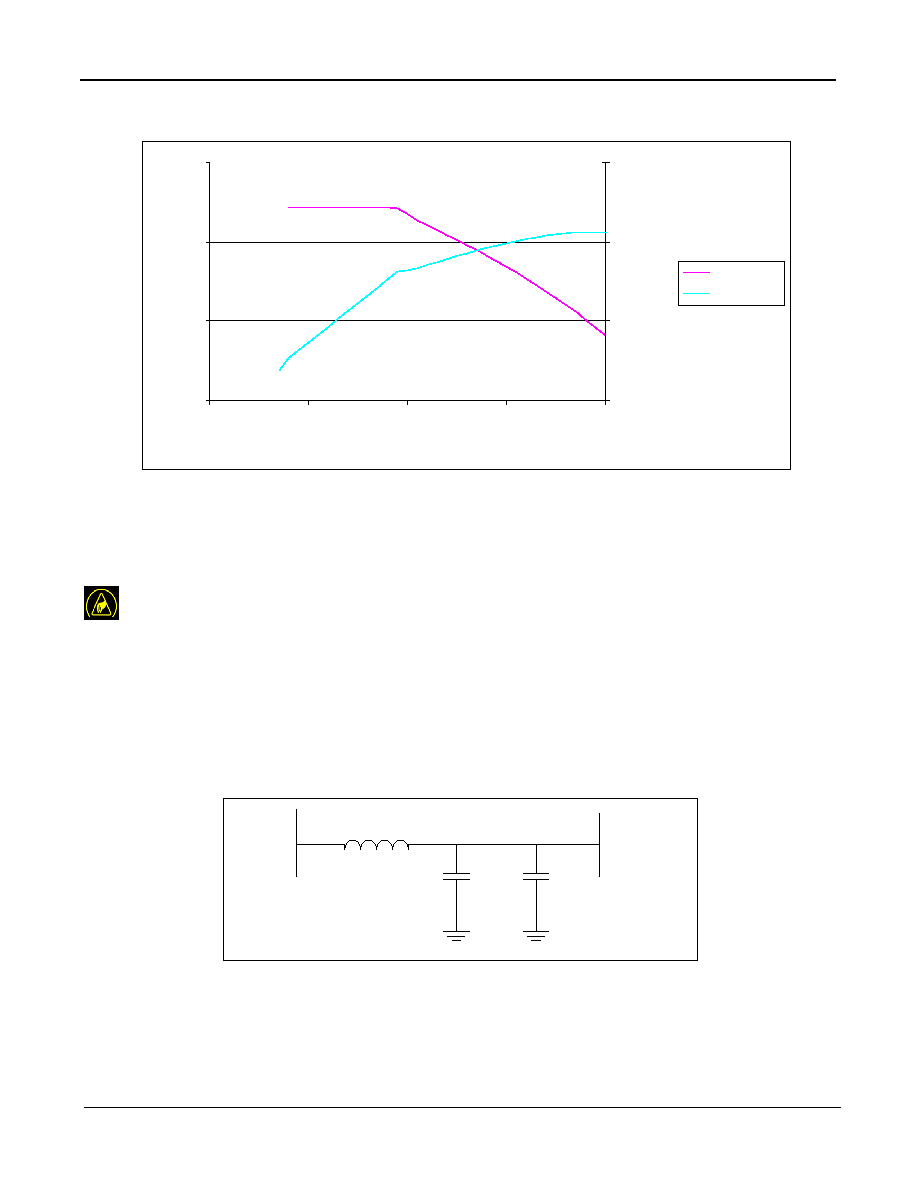
Figure 6 - Output Voltage vs Input Power
Application Guidelines
ESD handling
The receiver is sensitive to electrostatic discharges. When handling the device, precautions for ESD sensitive
devices should be taken. These precautions include use of ESD protected work area with wrist straps, controlled
work benches, floors etc.
Power Supply Filter
Power Supply decoupling capacitors are recommended for optimal performance of the receiver. A filter is
recommended to minimize power supply noise. See Figure 7.
Figure 7 - Recommended Power Supply Filter
0.1
1
10
100
0.0001
0.001
0.01
0.1
1
Pavg (m W)
Resp (kV
/
W)
0.01
0.1
1
10
Output (V)
Response
OIPvsOutput
C
0.1
µF
C
10nF
L
10
µH
Host
V
CC
PIN /
Preamp

Data Sheet
ZL60007
5
Zarlink Semiconductor Inc.
Data Outputs
The outputs Data and Data signals, are designed to drive a high load >500'
. It is recommended to use Mindspeed
MC2044C postamplifier (R
in
~4.5'
) together with ZL60007.
Figure 8 - Recommended Post Amplifier and Coupling Capacitors
ZL60007 output
MC2044C
C
10nF
C
10nF