
Product Specification
PS009318-1105
ZHX1810
Slim Series SIR
Transceiver
ZiLOG Worldwide Headquarters ∑ 532 Race Street ∑ San Jose, CA 95126-3432
Telephone: 408.558.8500 ∑ Fax: 408.558.8300 ∑
www.ZiLOG.com

PS009318-1105
This publication is subject to replacement by a later edition. To determine whether
a later edition exists, or to request copies of publications, contact:
ZiLOG Worldwide Headquarters
532 Race Street
San Jose, CA 95126-3432
Telephone: 408.558.8500
Fax: 408.558.8300
www.ZiLOG.com
ZiLOG is a registered trademark of ZiLOG Inc. in the United States and in other countries. All other
products and/or service names mentioned herein may be trademarks of the companies with which
they are associated.
Document Disclaimer
©2005 by ZiLOG, Inc. All rights reserved. Information in this publication concerning the devices,
applications, or technology described is intended to suggest possible uses and may be superseded.
ZiLOG, INC. DOES NOT ASSUME LIABILITY FOR OR PROVIDE A REPRESENTATION OF
ACCURACY OF THE INFORMATION, DEVICES, OR TECHNOLOGY DESCRIBED IN THIS
DOCUMENT. ZiLOG ALSO DOES NOT ASSUME LIABILITY FOR INTELLECTUAL PROPERTY
INFRINGEMENT RELATED IN ANY MANNER TO USE OF INFORMATION, DEVICES, OR
TECHNOLOGY DESCRIBED HEREIN OR OTHERWISE. Devices sold by ZiLOG, Inc. are covered
by warranty and limitation of liability provisions appearing in the ZiLOG, Inc. Terms and Conditions of
Sale. ZiLOG, Inc. makes no warranty of merchantability or fitness for any purpose. Except with the
express written approval of ZiLOG, use of information, devices, or technology as critical components
of life support systems is not authorized. No licenses are conveyed, implicitly or otherwise, by this
document under any intellectual property rights.

ZHX1810
Slim SIR Transceiver
PS009318-1105
Table of Contents
iii
Table of Contents
Description . . . . . . . . . . . . . . . . . . . . . . . . . . . . . . . . . . . . . . . . . . . . . . . . . . . . . 1
Features . . . . . . . . . . . . . . . . . . . . . . . . . . . . . . . . . . . . . . . . . . . . . . . . . . . . . . . 1
Block Diagram . . . . . . . . . . . . . . . . . . . . . . . . . . . . . . . . . . . . . . . . . . . . . . . . . . . 2
Pin Descriptions . . . . . . . . . . . . . . . . . . . . . . . . . . . . . . . . . . . . . . . . . . . . . . . . . 2
LEDA LED Driver Anode . . . . . . . . . . . . . . . . . . . . . . . . . . . . . . . . . . . . . . . . 3
TXD Transmit Data . . . . . . . . . . . . . . . . . . . . . . . . . . . . . . . . . . . . . . . . . . . . 3
RXD/Receive Data . . . . . . . . . . . . . . . . . . . . . . . . . . . . . . . . . . . . . . . . . . . . 3
SD Shutdown . . . . . . . . . . . . . . . . . . . . . . . . . . . . . . . . . . . . . . . . . . . . . . . . 3
VCC Positive Supply . . . . . . . . . . . . . . . . . . . . . . . . . . . . . . . . . . . . . . . . . . . 3
GND Ground . . . . . . . . . . . . . . . . . . . . . . . . . . . . . . . . . . . . . . . . . . . . . . . . . 3
TAB . . . . . . . . . . . . . . . . . . . . . . . . . . . . . . . . . . . . . . . . . . . . . . . . . . . . . . . . 3
Recommended Application Circuits . . . . . . . . . . . . . . . . . . . . . . . . . . . . . . . . . . 4
Electrical and Timing Specifications . . . . . . . . . . . . . . . . . . . . . . . . . . . . . . . . . . 5
Mechanical Drawings . . . . . . . . . . . . . . . . . . . . . . . . . . . . . . . . . . . . . . . . . . . . . 8
Soldering and Cleaning Recommendations . . . . . . . . . . . . . . . . . . . . . . . . . . . 11
Reflow Soldering . . . . . . . . . . . . . . . . . . . . . . . . . . . . . . . . . . . . . . . . . . . . . 11
Manual Soldering . . . . . . . . . . . . . . . . . . . . . . . . . . . . . . . . . . . . . . . . . . . . 11
Cleaning (Preferred) . . . . . . . . . . . . . . . . . . . . . . . . . . . . . . . . . . . . . . . . . . 11
Packing, Storage, and Baking Recommendations . . . . . . . . . . . . . . . . . . . . . . 12
Storage . . . . . . . . . . . . . . . . . . . . . . . . . . . . . . . . . . . . . . . . . . . . . . . . . . . . 12
Baking . . . . . . . . . . . . . . . . . . . . . . . . . . . . . . . . . . . . . . . . . . . . . . . . . . . . . 12
Moisture-Proof Packing . . . . . . . . . . . . . . . . . . . . . . . . . . . . . . . . . . . . . . . . 13
Taping Specifications . . . . . . . . . . . . . . . . . . . . . . . . . . . . . . . . . . . . . . . . . . . . 14
Ordering Information . . . . . . . . . . . . . . . . . . . . . . . . . . . . . . . . . . . . . . . . . . . . . 17
Customer Feedback Form . . . . . . . . . . . . . . . . . . . . . . . . . . . . . . . . . . . . . . . . . 18
Customer Information . . . . . . . . . . . . . . . . . . . . . . . . . . . . . . . . . . . . . . . . . 18
Product Information . . . . . . . . . . . . . . . . . . . . . . . . . . . . . . . . . . . . . . . . . . . 18
Return Information . . . . . . . . . . . . . . . . . . . . . . . . . . . . . . . . . . . . . . . . . . . . 18
Problem Description or Suggestion . . . . . . . . . . . . . . . . . . . . . . . . . . . . . . . 18

ZHX1810
Slim SIR Transceiver
PS009318-1105
List of Figures and Tables
iv
List of Figures
Figure 1. Slim SIR Transceiver Block Diagram . . . . . . . . . . . . . . . . . . . . . . . . . 2
Figure 2. Application Block Diagrams . . . . . . . . . . . . . . . . . . . . . . . . . . . . . . . . 4
Figure 3. I
F
-Ie Characteristics (0∞) . . . . . . . . . . . . . . . . . . . . . . . . . . . . . . . . . . 6
Figure 4. I
F
-LEDA Characteristics (0∞) . . . . . . . . . . . . . . . . . . . . . . . . . . . . . . . 7
Figure 5. Directive Characteristics (Emitting) . . . . . . . . . . . . . . . . . . . . . . . . . . 7
Figure 6. Directive Characteristics (Receiving) . . . . . . . . . . . . . . . . . . . . . . . . . 7
Figure 7. ZHX1810 Mechanical Drawing . . . . . . . . . . . . . . . . . . . . . . . . . . . . . 8
Figure 8. Alternative ZHX1810 Mechanical Drawing . . . . . . . . . . . . . . . . . . . . 9
Figure 9. Alternative ZHX1810 Mechanical Drawing . . . . . . . . . . . . . . . . . . . 10
Figure 10. ZHX1810 Packaging . . . . . . . . . . . . . . . . . . . . . . . . . . . . . . . . . . . . 13
Figure 11. ZHX1810 Reel Dimensions (Unit: mm) . . . . . . . . . . . . . . . . . . . . . . 14
Figure 12. ZHX1810 Tape Dimensions and Configuration (Unit: mm)
for Figure 7 . . . . . . . . . . . . . . . . . . . . . . . . . . . . . . . . . . . . . . . . . . . 15
Figure 13. Alternative ZHX1810 Tape Dimensions and Configuration (Unit: mm)
for Figure 8 . . . . . . . . . . . . . . . . . . . . . . . . . . . . . . . . . . . . . . . . . . . 16
Figure 14. Alternative ZHX1810 Tape Dimensions and Configuration (Unit: mm)
for Figure 9 . . . . . . . . . . . . . . . . . . . . . . . . . . . . . . . . . . . . . . . . . . . 16
List of Tables
Table 1.
Pin Out for the ZHX1810 Transceiver . . . . . . . . . . . . . . . . . . . . . . . . 2
Table 2.
Absolute Maximum Ratings . . . . . . . . . . . . . . . . . . . . . . . . . . . . . . . . 5
Table 3.
Recommended Operating Conditions . . . . . . . . . . . . . . . . . . . . . . . . 5
Table 4.
Electrical Characteristics . . . . . . . . . . . . . . . . . . . . . . . . . . . . . . . . . . 5

ZHX1810
Slim SIR Transceiver
PS009318-1105
1
Description
The ZILOG ZHX1810 is a low-profile version of ZiLOG's popular ZHX1010
1-meter transceiver. The transceiver is mechanically enhanced for ultra compact,
power-conscious portable products, such as mobile phones, portable printers,
handheld computers, and personal data assistants (PDAs). Designed to operate
using the IrDA-Data mode, the transceiver combines an infrared emitting diode
(IRED) emitter, a PIN photodiode detector, a digital AC coupled LED driver, and a
receiver/decoder in a single package.
The ZILOG ZHX1810 provides an efficient implementation of the SIR standard in
a small-outline footprint format. Application circuit space is also minimized, as only
three components are required.
ZHX1810 also features an independently controlled shutdown that minimizes cur-
rent draw to a maximum of 1
µA.
Features
∑
Compliant to IrDA Data Specification SIR
∑
Wide power supply voltage range, 2.4 to 5.5 V
∑
Minimum link distance, 1 M
∑
Low-power, listening current, 90
µA (typical) at 3.0 V
∑
Slim form factor (9.1 mm long x 3.8 mm wide x 2.73 mm high)
∑
Only two external components required
∑
Extended operating temperature range (≠30
∞
C to +85
∞
C)
∑
Meets IEC 825-1 Class 1 Eye Safety Specifications

ZHX1810
Slim SIR Transceiver
PS009318-1105
2
Block Diagram
Figure 1 is the block diagram for the Slim SIR transceiver.
Figure 1. Slim SIR Transceiver Block Diagram
Pin Descriptions
The ZHX1810 transceiver uses the pins listed in Table 1. The pins are described
in this section.
Table 1. Pin Out for the ZHX1810 Transceiver
Pin
Name
Function
I/O
1
LEDA
IRED anode
--
2
TXD
Transmitter input
I
3
RXD
Receiver output
O
4
SD
Enables shutdown mode
I
5
V
CC
Supply voltage
--
6
GND
Ground
--
--
TAB
Shield ground
--

ZHX1810
Slim SIR Transceiver
PS009318-1105
3
LEDA LED Driver Anode
(Power)
This output is connected to the LED anode. Current to the LED is sourced through
an external resistor.
TXD Transmit Data
(Input, active high)
This CMOS input is used to transmit serial data. This input has an internal pull-
down resistor that is disabled (open-circuited) during shutdown.
RXD/Receive Data
(Output, active low)
This output indicates received serial data. It is a tri-state, slew rate controlled
CMOS output (tri-stated during shutdown) driver capable of driving a standard
CMOS load. No external resistor is required.
SD Shutdown
(Input, active high)
This input is used to place the integrated circuit into shutdown mode. Module shut-
down current is influenced by the choice of capacitor used from V
CC
to ground.
V
CC
Positive Supply
(Power)
Connect to positive power supply (2.4≠5.5 V). Filter with a 0.33-
µF ceramic
bypass capacitor and terminating resistor as close as possible to the V
CC
pin.
GND Ground
(Power)
Connect to ground of the power supply. A solid ground plane is recommended for
proper operation.
TAB
(Shield)
The Shield tab must be soldered to the ground plane.

ZHX1810
Slim SIR Transceiver
PS009318-1105
4
Recommended Application Circuits
Figure 2 shows application block diagrams for the ZHX1810 transceiver.
Figure 2. Application Block Diagrams

ZHX1810
Slim SIR Transceiver
PS009318-1105
5
Electrical and Timing Specifications
Table 2 through Table 4 present the electrical and timing specifications for the
ZHX1810 transceiver.
Table 2. Absolute Maximum Ratings
Parameter
Symbol Minimum Maximum Unit Comment
Supply Voltage
V
cc
≠0.3
6.0
V
V
cc
, GND
Input Voltage
V
IN
GND≠0.3
V
cc
+0.3
V
TxD, SD
Output (External) Voltage
V
OUT
GND≠0.3
V
cc
+0.3
V
RxD
LED Current
I
LED
700
mA 20% duty cycle,
Ta=25 ∞C,
t
ON
<90
µ
S
Storage Temperature
T
ST
≠40
100
∞C
Solder Temperature
T
SOL
240
∞C
ESD
1,000
V
Table 3. Recommended Operating Conditions
Parameter
Symbol
Minimum
Maximum
Unit
Supply Voltage
V
cc
2.4
5.5
V
LED Voltage
V
LED
2.4
6.0
V
Ambient Operating Temperature
T
OP
≠30
85
∞C
Table 4. Electrical Characteristics
Parameter
Symbol Condition
Min
Typical
Max
Unit
Remarks
High-Level Input Voltage
V
IH
0.6 V
cc
V
cc
+0.5
V
TXD, SD
Low-Level Input Voltage
V
IL
≠0.5
0.2 V
cc
V
TXD, SD
High-Level Output Voltage V
OH
2.2
V
RxD
Low-Level Output Voltage V
OL
0.4
V
RxD
Transmitter Current
I
LED
300
mA
Listening Current
I
CC
90
150
µ
A
Receive Current
I
CC
90
150
µ
A
Unless otherwise noted: V
cc
=3.3 V, GND= 0 V, T
A
= 25 ∞C

ZHX1810
Slim SIR Transceiver
PS009318-1105
6
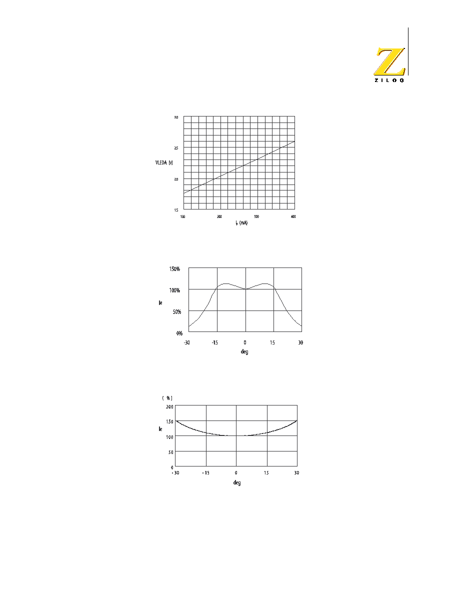
Figure 3 through Figure 6 show various electrical characteristics.
Figure 3. I
F
-Ie Characteristics (0∞)
Standby Current
I
STB
1
µ
A
SD=V
cc
,
TxD=0 V
Optical Rise/Fall Time
t
Rr
, t
Rf
100
nS
RxD Pulse Width
t
PWA
SIR=115.2
Kbps
1.1
1.6
3.9
µ
S
Power Shutdown Time
T
SD
1
µ
S
Startup Time
T
STU
200
µ
S
Receiver Latency
T
L
100
µ
s
Trans. Radiant Intensity
I
E
I
LED
=260 mA
40
100
mW/sr
h,
v<(+15
∞
)
Min. Threshold Irradiance
E
emin
V
cc
=3.3 V
2
3
µ
W/cm
2
h,
v<(+15
∞
)
Angle of Half Intensity
20
∞
Hor. and
Vert.
Light Pulse Rise, Fall Time t
or
, t
of
40
nS
Optical Pulse Width
t
OPW
20
µ
S
TxD="H"
Optical Overshoot
t
OPO
3
%
Peak Wavelength
P
870
nm
Table 4. Electrical Characteristics (Continued)
Parameter
Symbol Condition
Min
Typical
Max
Unit
Remarks
Unless otherwise noted: V
cc
=3.3 V, GND= 0 V, T
A
= 25 ∞C
ZHX1810
Slim SIR Transceiver
PS009318-1105
7
Figure 4. I
F
-LEDA Characteristics (0∞)
Figure 5. Directive Characteristics (Emitting)
Figure 6. Directive Characteristics (Receiving)
ZHX1810
Slim SIR Transceiver
PS009318-1105
8
Mechanical Drawings
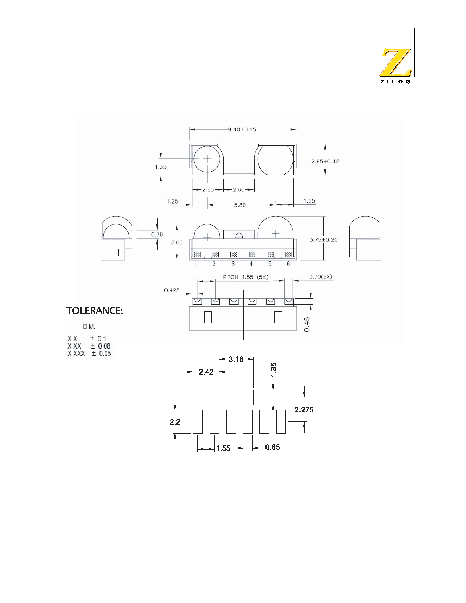
In order to achieve the lowest possible costs and lead times, ZiLOG maintains
multiple assembly facilities. The mechanical drawings for these transceivers are
shown in Figure 7, Figure 8, and Figure 9. These devices, which show minor
mechanical differences, are functionally equivalent in every way and meet all
ZiLOG and IrDA standards and specifications. All ZHX1810 devices use the iden-
tical solder pad layout. Although reels are never mixed, ZiLOG reserves the right
to ship from either facility in order to meet delivery requirements. When designing
an IrDA subsystem, the user is advised to allow mechanical clearance for all ver-
sions of the IrDA transceiver.
Figure 7. ZHX1810 Mechanical Drawing

ZHX1810
Slim SIR Transceiver
PS009318-1105
9
Figure 8. Alternative ZHX1810 Mechanical Drawing
ZHX1810
Slim SIR Transceiver
PS009318-1105
10
Figure 9. Alternative ZHX1810 Mechanical Drawing

ZHX1810
Slim SIR Transceiver
PS009318-1105
11
Soldering and Cleaning Recommendations
Follow these recommendations to maintain the performance of the ZHX1810
transceiver.
Reflow Soldering
Please refer to ZiLOG's Lead-Free Solder Reflow: Packaging
Application Note (AN0161, http://www.zilog.com/docstools.asp)
for more information about the solder profile.
Manual Soldering
∑
Use 63/37 or silver solder.
∑
Use a soldering iron of 25 W or smaller. Adjust the temperature of the
soldering iron below 300 ∞C.
∑
Finish soldering within 3 seconds.
∑
Handle only after ZHX1810 has cooled off.
Cleaning (Preferred)
Perform cleaning after soldering under the following conditions:
∑
Cleaning agent: Alcohol
∑
Temperature and time: 30 seconds below 50 ∞C or 3 minutes below 30 ∞C
∑
Ultrasonic cleaning: Below 20 W
Additional cleaning methods can also be used. Please see the www.zilog.com
documentation pages for details.
Note:

ZHX1810
Slim SIR Transceiver
PS009318-1105
12
Packing, Storage, and Baking Recommendations
Follow these recommendations to maintain the performance of the ZHX1810
transceiver.
Storage
To avoid moisture absorption, ZHX1810 reels must remain in the original,
unopened moisture-proof packing. Parts must be soldered within 72 hours after
unpacking. Reels that have been unpacked, but will not be soldered within 72
hours, must be stored in a desiccator.
Baking
Parts that have been stored over 12 months or unpacked over 72 hours must be
baked under the following guidelines.
Reels
60 ∞C for 48 hours or more
Loose Parts
∑
100 ∞C for 4 hours or more
or
∑
125 ∞C for 2 hours or more
or
∑
150 ∞C for 1 hour or more

ZHX1810
Slim SIR Transceiver
PS009318-1105
13
Moisture-Proof Packing
In order to avoid moisture absorption during transportation and storage, ZHX1810
reels are packed in aluminum envelopes (see Figure 10) that contain a desiccant
with a humidity indicator. While this packaging is an impediment to moisture
absorption, it is by no means absolute, and no warranty is implied. The user should
store these parts in a controlled environment to prevent moisture entry. Please read
the label on the aluminum bag for indicator instructions.
Figure 10. ZHX1810 Packaging

ZHX1810
Slim SIR Transceiver
PS009318-1105
14
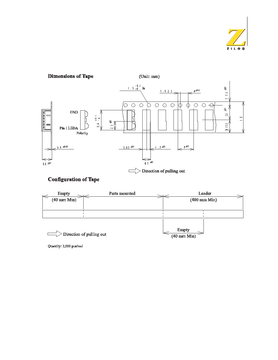
Taping Specifications
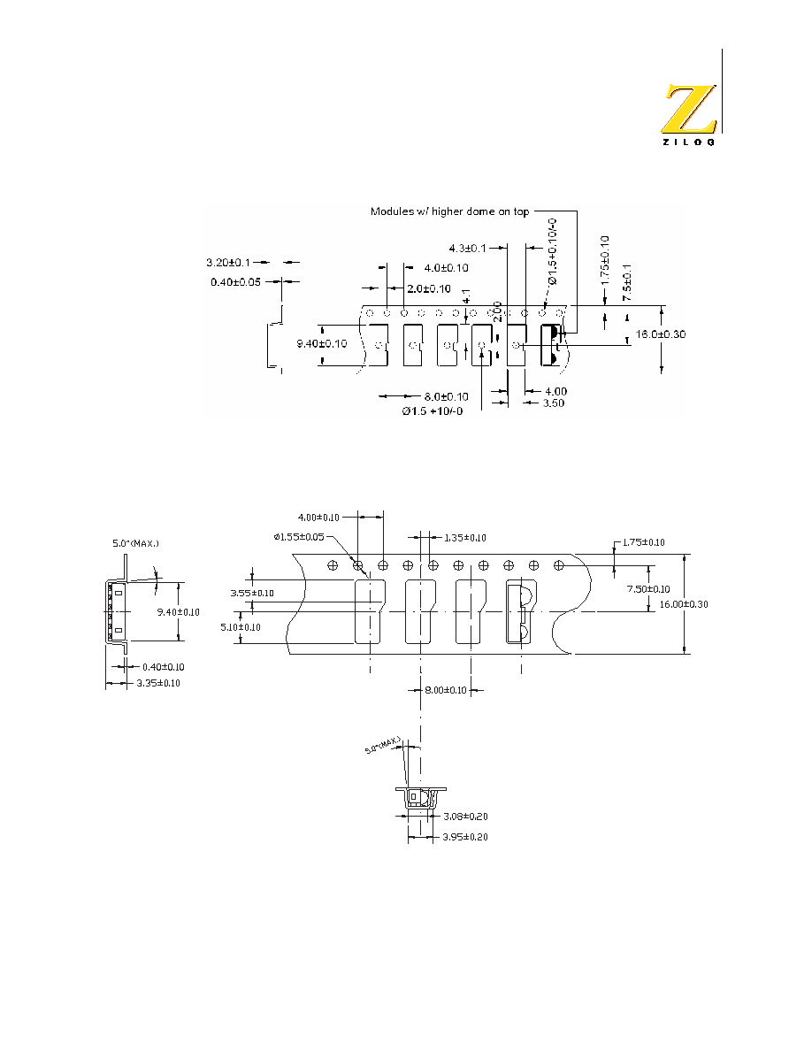
Figure 11 shows the reel dimensions for the ZHX1810. Figure 12, Figure 13, and
Figure 14 show the tape dimensions and configuration for the ZHX1810.
Figure 11. ZHX1810 Reel Dimensions (Unit: mm)
ZHX1810
Slim SIR Transceiver
PS009318-1105
15
Figure 12. ZHX1810 Tape Dimensions and Configuration (Unit: mm) for Figure 7
ZHX1810
Slim SIR Transceiver
PS009318-1105
16
Figure 13. Alternative ZHX1810 Tape Dimensions and Configuration (Unit: mm) for
Figure 8
Figure 14. Alternative ZHX1810 Tape Dimensions and Configuration (Unit: mm) for
Figure 9

ZHX1810
Slim SIR Transceiver
PS009318-1105
17
Ordering Information
To order ZHX1810, use ZiLOG part number ZHX1810MV115THTR.
In order to ensure the lowest possible lead times, ZiLOG uses
two different fab sources for the transceiver IC. Both of these
ICs have been extensively tested and qualified to meet the
ZHX1810 transceiver specifications.
All ZiLOG devices are available lead free. Since 2005,
ZHX1810 has been manufactured with lead-free components.
When ordering from your ZiLOG distributor, there is a
possibility that the parts containing lead might be shipped. To
ensure that you receive lead-free devices, please use part
number ZHX1810MV115TH2090TR. These devices meet or
exceed RoHS Directive 2002/95/EC. For additional
information, please see the ZiLOG Quality and Reliability web
page at http://www.zilog.com/quality/index.asp.
Notes:

ZHX1810
Slim SIR Transceiver
PS009318-1105
18
Customer Feedback Form
If you experience any problems while operating the ZHX1810 transceiver, or if you note
any inaccuracies while reading this product specification, please copy and complete this
form, then mail or fax it to ZiLOG (see "Return Information," below). We also welcome
your suggestions!
Customer Information
Product Information
Return Information
ZiLOG
System Test/Customer Support
532 Race Street
San Jose, CA 95126-3432
Fax: (408) 558-8300
Web: www.zilog.com
Problem Description or Suggestion
Provide a complete description of the problem or your suggestion. If you are reporting a
specific problem, include all steps leading up to the occurrence of the problem. Attach
additional pages as necessary.
_______________________________________________________________________________
_______________________________________________________________________________
_______________________________________________________________________________
_______________________________________________________________________________
Name
Country
Company
Phone
Address
Fax
City/State/Zip
email
Serial # or Board Fab #/Rev #
Software Version
Document Number
Host Computer Description/Type